
How Do You Troubleshoot Inconsistent CMM Measurements?
Inconsistent CMM measurements should be treated as a measurement-system problem until evidence isolates a specific cause. A coordinate measuring machine can repeat poorly because of environmental change, unstable part location, probe behavior, machine condition, software configuration, or variation in the inspection routine itself. Repeating the same program without controlling those inputs may create more data, but not more confidence.
The practical question is not simply whether two results differ. It is whether the observed spread is large enough to affect a conformity decision, and whether that spread originates in the part or in the measurement process. That distinction is essential when tolerances are tight, results are shared across sites, or inspection records support aerospace, medical, semiconductor, or other controlled manufacturing activities.
Start by defining what “inconsistent” means
Different symptoms point to different failure mechanisms. A result that drifts gradually through the day is not the same problem as a result that changes when the part is re-fixtured, when a different stylus is used, or when a program is rerun after recalibration.
Before adjusting the machine or editing the program, document a short set of facts:
- Which characteristic is unstable: size, location, form, profile, angle, or datum-related position?
- Is the variation random, directional, time-dependent, or linked to a particular setup?
- Does the discrepancy appear on one part, one family of parts, or all inspected work?
- Does it occur on one CMM only, or when results are compared across machines or facilities?
- Can the condition be reproduced with a calibrated artifact, such as a ring gauge, sphere, gauge block, or certified master part?
This initial record prevents a common mistake: treating every disagreement as an accuracy issue. A CMM can be accurate under its stated operating conditions and still deliver unreliable production results if the setup, part, probe, or evaluation logic is not controlled.
Separate repeatability from reproducibility
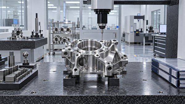
A useful first test is to run the same part repeatedly without removing it from the fixture. If the reported values move materially, the likely sources are machine behavior, probing, environmental instability, filtering, or program execution. If results are stable until the part is removed and set again, fixturing, datum establishment, part deformation, or handling becomes more likely.
Then repeat the inspection with another qualified operator or another validated setup. This separates repeatability—the consistency of repeated results under unchanged conditions—from reproducibility—the consistency obtained when normal operational variables change. Both matter. A measurement method that gives stable values only when one experienced operator uses one exact setup may be unsuitable for routine quality control.
Where measurement-system analysis is required, a formal gauge repeatability and reproducibility study may be appropriate. However, a GR&R exercise should not be used as a substitute for basic troubleshooting. If thermal conditions, fixture design, probe qualification, or datum logic are already suspect, the study will quantify a disturbed process rather than explain it.
Check temperature before blaming the CMM
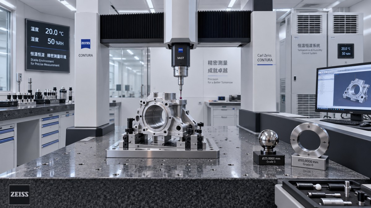
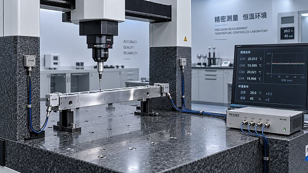
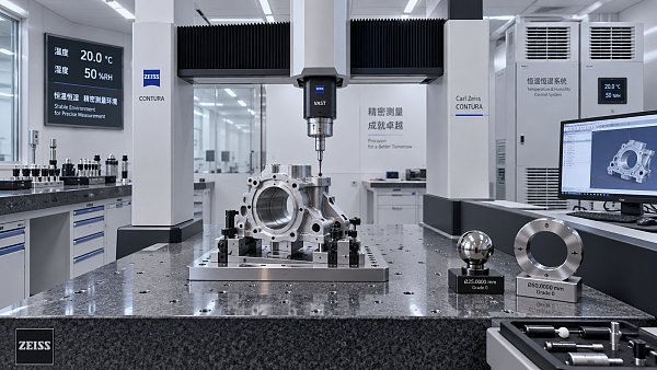
Temperature is among the most persistent causes of inconsistent dimensional results because both the part and the machine structure expand or contract. The reference temperature commonly used for dimensional metrology is 20°C, as reflected in ISO 1. The issue is not merely whether the CMM room feels climate-controlled. The relevant questions are whether the air temperature is stable, whether the workpiece has reached equilibrium, and whether temperature gradients exist across the machine volume or within the part.
A part transferred from machining, washing, packaging, or a warmer warehouse may retain a temperature different from the inspection environment. Large parts, dense materials, and assemblies with mixed materials can take substantial time to stabilize. Measuring a warm part repeatedly as it cools can produce an apparent trend that resembles machine drift.
Thermal effects become more visible on long dimensions, high-expansion materials, and tolerances that consume only a small fraction of the part’s nominal size. Compensation can be valid when the machine, sensors, material coefficient, and software implementation are properly controlled. It is not a universal correction for poorly managed conditions. Incorrect material coefficients, poor sensor placement, or a non-uniform part temperature can make compensation less trustworthy than a controlled equilibration process.
Review environmental logs alongside inspection timestamps. Look for HVAC cycling, direct sunlight, air discharge paths, heat from nearby equipment, open doors, and changes in machine-room occupancy. A sudden shift that corresponds to a temperature event is more informative than an isolated out-of-tolerance result.
Verify the part is stable and constrained correctly
A fixture should locate a component without forcing it into a shape it does not naturally hold. This is especially important for thin-walled castings, sheet-metal components, plastic parts, compliant seals, additively manufactured structures, and parts with unfinished contact surfaces. Excess clamp force can bend the workpiece; insufficient support can allow it to move under probe contact. Either condition can create inconsistent geometry.
The fixture also has to support the datum scheme used in the inspection plan. If the physical locating points do not correspond to the functional or drawing datums, the CMM may establish a mathematically valid alignment that does not represent how the part functions or how it is assembled. The result can be a persistent disagreement between incoming inspection, in-process inspection, and assembly performance.
Check for burrs, contamination, chips, oil films, damaged locating surfaces, and incomplete seating. A part that rests on three nominal points but actually contacts a chip on one point can rotate by a small amount; that small rotation may create large positional changes at distant features. Re-fixture the part several times and compare the alignment values, not just the final characteristic. If the datum origin or rotational alignment changes materially, investigate the setup before modifying tolerances or program logic.
Probe qualification is not a one-time administrative task
Probe-system errors often appear after a stylus change, collision, battery or head service, temperature change, or program update. Qualification establishes the relationship between the probing system and the reference artifact. If that relationship is no longer valid, every subsequent coordinate can carry a systematic error.
Confirm that the active probe configuration in the program matches the physical stylus assembly: stylus length, ball diameter, extension, angular orientation, probe head index, and qualification record. A program can run successfully while calling an incorrect stylus definition or a qualification generated under different conditions.
Long, slender, or heavily offset styli deserve additional scrutiny. They can introduce bending, dynamic response, and accessibility issues that do not affect a short, rigid stylus. A large stylus ball may bridge local surface features; a small ball may be more sensitive to roughness, debris, and local defects. Neither choice is inherently better. The selected stylus must fit the specified feature, surface condition, access path, and uncertainty requirement.
Probe contact force and speed also matter. Excessive probing speed or force can displace compliant parts, deflect stylus components, or cause unstable triggering on difficult surfaces. Conversely, a very slow routine may reduce throughput without solving the real problem. Compare results using a controlled reduction in speed and force. If the values stabilize, investigate probing dynamics and part compliance rather than assuming the feature itself is changing.
Use calibrated artifacts to distinguish machine error from application error
A certified artifact is valuable because it offers a known geometry independent of the production part. Measure it in different areas of the machine volume, with the same probe and program conditions used for the suspect inspection. This can reveal whether the inconsistency follows a region of travel, a particular probe orientation, or a specific measurement strategy.
Artifacts do not replace manufacturer-recommended performance verification or periodic calibration. They provide a focused diagnostic check. If a reference sphere, ring, or length standard gives stable results while production parts do not, the machine may not be the primary source. Attention should move to part condition, fixturing, datum strategy, access, surface texture, or program interpretation.
If the artifact also gives inconsistent values, preserve the evidence: environmental records, probe status, error messages, machine position, and repeat runs. Service decisions are more effective when the symptom is documented rather than described only as “the CMM is inaccurate.”
Interrogate the inspection program, not just the reported result
Many apparent CMM discrepancies are evaluation discrepancies. Two programs can touch the same part and produce different values because they use different datum constructions, feature fitting methods, point distributions, outlier handling, filters, compensation rules, or reporting units.
For example, a diameter derived from a sparse set of points may not match a result from a scanning path on a non-ideal bore. A least-squares fit, maximum inscribed fit, minimum circumscribed fit, and minimax fit answer different geometric questions. The appropriate method depends on the drawing requirement, applicable GD&T standard, functional intent, and agreed inspection practice. Selecting a fit merely because it yields a favorable result undermines traceability.
Datum alignment deserves the same discipline. A 3-2-1 alignment, best-fit alignment, iterative alignment, and datum feature simulation may each be legitimate in particular circumstances, but they are not interchangeable. When supplier and customer reports disagree, compare the alignment construction point by point before comparing final values. Differences in datum precedence, clocking constraints, or material boundary treatment can explain a substantial portion of the disagreement.
Review the program after software upgrades or postprocessor changes. Default settings for filtering, reporting precision, probe approach, collision avoidance, or feature calculation may change between versions. Lock validated programs under revision control, and maintain clear records of who changed what, why, and against which reference part or approved dataset the change was verified.
Surface condition and feature accessibility can distort the result
CMM measurement assumes that the probe can reach the intended surface and that the surface supports the selected measurement strategy. Burrs, porous coatings, weld spatter, plating variation, rough machining marks, soft materials, and contamination can make individual contact points unrepresentative. A clean-looking surface is not necessarily a metrologically stable surface.
Do not solve this by deleting inconvenient points without a defined rule. If outlier rejection is permitted, its criteria should be established before routine inspection and applied consistently. Otherwise, the inspection result becomes dependent on subjective operator judgment.
Accessibility must also be checked in three dimensions. A stylus may contact the nominal feature while approaching at an angle that causes side contact, shanking interference, or poor normality. In multi-sensor systems, optical focus, reflectivity, edge-detection settings, and surface finish can introduce their own sources of variation. Results from tactile and optical sensors should not be assumed equivalent unless their measurement strategies have been validated for the feature in question.
Examine maintenance, verification, and machine health in context
Machine calibration status is necessary but not sufficient. A current certificate does not guarantee that the CMM has remained unaffected by collisions, contamination, air-bearing issues, cable wear, vibration, compressed-air quality problems, or changes in installation conditions since its last verification.
Look for signs that narrow the diagnosis: unusual noise during travel, inconsistent probe-head indexing, repeatable error in one axis direction, poor behavior near one area of the measuring volume, or problems that began after a collision or relocation. Check the manufacturer’s prescribed interim verification routines and confirm that the machine is installed and operated within its specified environmental limits.
Vibration can be overlooked when the CMM is located near machining centers, material handling routes, compressors, or building services. It may not affect every measurement. Its effect can be strongest during scanning, at certain travel speeds, or when measuring fine form characteristics. A time correlation between production activity and inspection variation is worth investigating.
Build a controlled response rather than adjusting everything at once
The fastest route to a defensible answer is to change one variable at a time. A practical sequence is to stabilize the room and workpiece, clean and re-seat the part, confirm fixture constraint, requalify the probe, verify the same program against a calibrated artifact, and then compare alignment and feature-evaluation settings. Each action should have a recorded result.
Avoid simultaneous changes such as requalifying the probe, editing the program, moving the fixture, and applying temperature compensation in one attempt. If the readings improve, the cause remains unknown; if they worsen, there is no reliable rollback point. Controlled troubleshooting may feel slower in the moment, but it avoids repeated disputes over measurement validity and unnecessary reinspection.
The final outcome should be more specific than “the CMM was fixed.” It should identify the confirmed cause, the evidence supporting it, the correction applied, and the control needed to prevent recurrence. That control may be a workpiece soak requirement, a fixture revision, a probe qualification trigger, a locked evaluation method, a defined cleaning instruction, or a revised verification interval.
Reliable CMM measurement is achieved when machine capability, thermal control, part restraint, probing strategy, software logic, and documented procedure all support the same measurement decision. When those elements are aligned, the reported value becomes not merely repeatable on screen, but defensible across shifts, sites, suppliers, and quality reviews.
Taglist:
Recent Articles
 2026.10.17Choosing a microfluidic probe manufacturer for stable flow confinementChoose a micro fluidic probe manufacturer with proven flow confinement. Compare geometry, flow control, validation, and repeatability to find the right fit for your application.
 2026.10.16What does measurement accuracy specified as % of full scale mean?Understand measurement specification accuracy as % of full scale. Learn to calculate error, compare sensor ranges, and choose the right instrument with confidence.
 2026.10.15How temperature affects high-accuracy dimensional analysis systemsDiscover how temperature affects high accuracy dimensional analysis systems, and learn practical ways to control thermal drift, improve compensation, and verify measurement accuracy.
 2026.10.14How air pressure affects precision pneumatic actuator repeatabilityPrecision Pneumatic actuator repeatability depends on more than supply pressure. Discover how pressure, friction, and flow affect positioning—and how to improve consistency in your application.
 2026.10.13How to choose a packaging manufacturer for small production runsChoose a packaging manufacturer for small production runs with confidence. Discover how to compare costs, verify samples, and secure quality packaging without excess inventory.
 2026.10.12Ultra-Pure Silane Gas for PECVD: Linking Impurities to Film DefectsQualify ultra-pure silane gas for PECVD with confidence. Learn how impurities affect film defects and use gas analysis, delivery checks, and film testing to set reliable acceptance limits.
 2026.10.12Qualifying an Ultra-Pure Silane Gas Manufacturer: Batch Consistency and TraceabilityQualify an ultra-pure silane gas manufacturer with confidence. Learn how to verify batch consistency, analytical results, and cylinder traceability to reduce sourcing risks.
 2026.10.12Choosing an Ultra-Pure Silane Gas Supplier: Lead Times, Delivery, and Backup SupplyChoose an ultra-pure silane gas supplier with reliable lead times, compliant delivery, and qualified backup supply. Learn what to verify to protect production and reduce supply risks.
 2026.10.12Ultra-Pure Chemicals in Latin America: What Shapes Regional Supply and Demand?Ultra-pure chemicals Latin America: explore demand drivers, qualified supply, and purity risks to uncover smarter sourcing and investment opportunities.
 2026.10.12How Do You Compare ALD/CVD Suppliers for Process Consistency?How do I compare semiconductor manufacturing suppliers for process consistency? Discover how to assess ALD/CVD film quality, run-to-run stability, and drift controls to select with confidence.
 2026.10.12What Materials Data Is Needed to Qualify a New PVD Target Supplier?Which material science data is essential before qualifying a new supplier? Discover PVD target checks for purity, microstructure, density and bond integrity to qualify suppliers with confidence.
 2026.10.12What Should a Private-Label Photoresist Quality Agreement Include?Build a stronger private label manufacturing quality agreement for photoresist. Discover essential clauses for specifications, batch release, change control, and traceability.
 2026.10.12How Much Does an Optical Tweezers System Cost?Explore optical tweezers system price ranges, key cost drivers, and ownership expenses. Compare configurations and learn how to choose the right setup for your research budget.
 2026.10.12How to size commercial refrigerators for a restaurant kitchenDiscover how commercialrefrigerators should be sized for peak demand, smarter workflow, food safety, and reliable restaurant kitchen performance.
 2026.10.11How procurement planning reduces supply risk in Latin AmericaProcurement planning Latin America helps reduce supply risk with supplier qualification, import readiness, inventory controls, and contingency sourcing.
 2026.10.10How to build a supplier capability evaluation scorecard for critical partsSupplier capability evaluation scorecard: build a risk-based framework with gates, evidence, and weighted criteria to qualify critical-part suppliers with confidence.
 2026.10.09When do sub micron pneumatic actuators improve metrology repeatability?Sub micron pneumatic actuators for metrology improve repeatability by reducing friction, controlling contact force, and accelerating settling time. Discover when they deliver measurable inspection gains.
 2026.10.08How to assess measurement uncertainty from a precision metrology supplierPrecision metrology supplier guide: assess measurement uncertainty, traceability, environmental effects, calibration, and decision rules for reliable results.
 2026.10.07Metrology application notes for choosing CMM probe strategiesMetrology application notes for selecting CMM probe strategies, improving accuracy, access, repeatability, and confidence in complex feature inspection.
 2026.10.06What refresh rate do VR headsets need to reduce motion sicknessVR headsets need at least 90Hz to help reduce motion sickness. Discover why stable frame rates, low latency, and 120Hz support can deliver smoother, more comfortable VR experiences.
 2026.10.05What drives nano-indentation systems cost for a new lab?Nano-indentation systems cost: discover the real budget drivers for a new lab, from configuration and site readiness to software, calibration, and service.
 2026.10.04When does a micro fluidic probe OEM need custom channel geometry?Micro fluidic probe OEM guide: learn when custom channel geometry improves confinement, shear control, reagent savings, and process reliability.
 2026.10.03How to prevent cross-contamination in semiconductor gas handlingSemiconductor Gas Handling best practices to prevent cross-contamination, protect gas purity, improve process stability, and strengthen fab safety.
 2026.10.02How healthcare engineering improves the accuracy of diagnostic equipmentHealthcare engineering improves diagnostic accuracy through precision design, calibration, fluid control, and traceable validation for reliable clinical results.
 2026.10.01When does a steel-frame vibration isolation table provide enough stability?Vibration isolation table steel frame stability explained: assess stiffness, resonance, payload, and isolator performance for precise, reliable measurements.
 2026.09.30How probe station procurement alerts prevent costly supply delaysProbe station procurement alerts help teams spot configuration risks, lead-time changes, and compliance issues early—protecting test schedules and avoiding costly supply delays.
 2026.09.29How Do You Troubleshoot Inconsistent CMM Measurements?How do I troubleshoot inconsistent CMM measurements? Discover practical checks for temperature, fixturing, probes, programs, and machine health to improve confidence.
 2026.09.29How Often Should a Laser Interferometer System Be Calibrated?How often should a laser-interferometer system be calibrated? Explore risk-based intervals, traceability, verification checks, and compliance tips for precision measurements.
 2026.09.29Is Private Label Manufacturing Suitable for Regulated Components?Is private label manufacturing suitable for regulated components? Explore traceability, quality controls, change management, and supplier qualification essentials.
 2026.09.29How Can Procurement Planning Reduce Single-Source Supply Risk?How can procurement planning reduce single-source supply risk? Discover practical strategies for qualifying alternatives, mapping dependencies, building buffers, and protecting critical operations.
 2026.09.29What Should a Precision Manufacturing Supplier Audit Include?What should be included in a precision manufacturing supplier audit? Explore essential checks for process capability, metrology, traceability, and risk control.
 2026.09.29How Do Export Controls Affect Semiconductor Equipment Lead Times?How do export controls affect semiconductor equipment lead times? Discover licensing, screening, supplier, and service risks—and plan smarter to protect fab schedules.
 2026.09.29What Maintenance Does a Micro-Manipulation System Need?What maintenance does a micro-manipulation system need? Explore calibration, cleaning, motion checks, cable care, and environmental controls for reliable precision.
 2026.09.29Microdynamics in Precision Motion: What Engineers Need to MeasureMicrodynamics in precision motion: learn what engineers must measure to control vibration, settling, friction, compliance, and servo response for reliable nanometer-level results.
















FILTER_CORE
REF_NO: 0042
Editors' Picks
- 00
0000-00
Choosing a microfluidic probe manufacturer for stable flow confinement - 00
0000-00
What does measurement accuracy specified as % of full scale mean? - 00
0000-00
How temperature affects high-accuracy dimensional analysis systems - 00
0000-00
How air pressure affects precision pneumatic actuator repeatability