
Metrology application notes for choosing CMM probe strategies
A CMM inspection plan can appear sound until the probe reaches a deep bore, a narrow groove, a thin-wall feature, or a reflective surface. The program may still run, yet the result can be slow, unstable, or difficult to defend during a technical review. A probe strategy should therefore not begin with the fastest available sensor or the longest stylus assembly. It should begin with the functional requirement of each feature, the allowable measurement uncertainty, and the physical path needed to reach that feature without creating excessive probing force, deflection, collision risk, or alignment error.
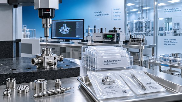
For technical evaluators, the practical answer is to select CMM probe strategies feature by feature, then validate them as a complete system. Use discrete tactile probing when datum control, form-related verification, and clearly defined point locations are central; use scanning when surface form or dense profile information matters; use optical or non-contact sensing where contact could distort the part or where coverage requirements outweigh tactile access. The final strategy must also account for stylus stiffness, qualification behavior, thermal conditions, and the inspection cycle’s intended purpose.
Start with the inspection decision, not the probe catalogue
The same component may require several sensing approaches. A precision-machined housing, for example, can contain datum planes, threaded holes, internal diameters, sealing lands, small radii, and freeform surfaces. Treating all features with one stylus and one measurement mode often produces an inspection program that is easy to create but hard to trust.
Before choosing a probe configuration, divide the drawing or model requirements into measurement tasks. The most useful initial questions are:
- Which features establish the part coordinate system, and which features are evaluated relative to that system?
- Is the requirement a size, location, orientation, form, profile, or surface condition requirement?
- Does the feature need a few repeatable points, or enough data to characterize its full geometry?
- Can the part tolerate contact force without movement, deformation, marking, or damage?
- What access restrictions are created by walls, adjacent geometry, cavities, or fixturing?
- How much uncertainty can be assigned to the measurement method relative to the functional tolerance?
This classification prevents a recurring error in metrology application notes: choosing a probe based only on nominal feature size. A small ball stylus may physically fit into a feature, but it may not provide a stable or representative result. Conversely, a larger stylus may provide better repeatability on an accessible surface while being unsuitable for a narrow radius or recessed wall.
Match probe mode to the geometry being evaluated
Discrete-point tactile probing
Touch-trigger or discrete-point probing is often appropriate for prismatic parts, datum establishment, hole centers, plane location, and geometric tolerances where a controlled point pattern is sufficient. It is comparatively straightforward to program, and it can provide robust results on rigid, well-accessed surfaces. The limitation is not that it measures only a small number of points; the limitation is that the selected points may miss local defects, waviness, or form variation that affects function.
A hole evaluated from a limited point set may meet a reported diameter and position result while still containing lobing or taper not captured by the sampling pattern. When the drawing requirement, downstream assembly risk, or process history suggests that form matters, increase the point pattern or consider scanning. More points are not automatically better, however. They increase cycle time and can amplify the influence of unstable fixturing, contamination, or inconsistent approach direction.
Continuous scanning
Scanning is useful when the inspection decision depends on a dense representation of a surface: cylinders requiring roundness or straightness assessment, cam profiles, sealing surfaces, airfoil sections, complex transitions, or form-critical freeform geometry. A scanning probe follows the surface while collecting many data points, making it possible to distinguish a local defect from a broader geometric trend.
Its value depends on method control. Probe force, scanning speed, filtering, point density, and evaluation software settings can change the reported result. A scan performed too quickly on a compliant part may reflect dynamic response rather than actual form. A scan with poorly selected filtering may either hide meaningful texture-related variation or report noise as form error. The inspection plan should define not only where the scan runs but also how the data are processed and compared with the specification.
Optical and non-contact methods
Optical probes, cameras, laser systems, and other non-contact sensors can be suitable for soft materials, thin sections, delicate surfaces, or features that must be measured without physical contact. They can also support broad surface coverage where tactile scanning would be impractical. Their limitations are different rather than absent. Surface reflectivity, translucency, color, edge condition, line-of-sight obstruction, and environmental light can affect data quality.
Non-contact measurement should not be selected solely because it is faster. Confirm how the sensor detects the target material, whether the required edge definition is repeatable, and whether the data treatment is compatible with the drawing requirement. A visually clear edge is not always a metrologically stable edge.

Stylus selection is an uncertainty decision
Stylus assemblies determine whether the machine can reach a feature, but they also influence stiffness, dynamic behavior, collision clearance, and qualification reliability. The shortest practical stylus is usually the preferred starting point because longer assemblies are more susceptible to bending and vibration. Yet a short stylus may force an approach angle that causes shaft contact, misses a hidden surface, or prevents access around an obstruction.
Ball diameter requires a similar trade-off. A larger ball can average minor surface texture and may be more stable on open, relatively smooth geometry. A smaller ball reaches tighter radii and narrow grooves but is more sensitive to roughness, contamination, and local surface irregularities. The ball must also be selected with the feature’s theoretical contact geometry in mind. A ball that is too large can bridge a concave radius or fail to access the intended flank; one that is too small may follow surface texture rather than the functional envelope.
Multi-stylus configurations can reduce indexing time and improve access to opposing faces or features at different angles. They should be justified by repeatability and cycle-time needs, not simply by convenience. Larger assemblies increase collision complexity and can make qualification more sensitive to temperature change, mounting condition, or accidental contact. Each active tip must be qualified in the configuration and orientation used for measurement.
Datum strategy determines whether feature results mean anything
A probe strategy cannot compensate for a weak alignment strategy. When a part is located on a fixture, the CMM program must distinguish between the production locating scheme and the datum reference frame defined by the engineering requirement. These may align closely, but they are not automatically interchangeable.
Establish primary, secondary, and tertiary datums using enough points and enough spatial distribution to resist local anomalies. For a primary plane, points clustered in one small area can produce a mathematically valid plane that does not represent the functional datum surface. For a cylindrical datum, the probing pattern should be sufficient to determine axis location and orientation without allowing a local burr, interrupted surface, or taper to dominate the alignment.
Probe approach direction also matters. Reversing approach direction on a surface can change the effect of pretravel, surface contamination, stylus bending, and contact dynamics. For tightly controlled features, keep the direction consistent where possible and verify that the chosen approach is physically representative of the intended contact condition. This is especially relevant for opposing faces, thin ribs, and parts with variable surface finish.
Build the strategy around access before programming the cycle
Collision avoidance is not a final simulation task; it is part of strategy selection. A probe that reaches every feature only through narrow clearances may create a program with excessive moves, frequent head indexing, and high collision exposure. Review the complete envelope: stylus ball, stem, extensions, probe body, rotary head, fixtures, clamps, and neighboring features. A path that clears the measured feature may still fail at the approach or retract stage.
Access review is particularly important with angled holes, undercuts, blade-like geometries, and dense multi-feature components. In these situations, a qualified stylus orientation may be technically possible but operationally fragile. A more robust method may involve repositioning the workpiece, changing the fixture, splitting the inspection into setups, or using a complementary sensor. Reducing one setup is not beneficial if it creates an unacceptably sensitive measurement path.
Control the factors that can mimic part variation
When repeated measurements disagree, the probe is often blamed first. The cause may instead be thermal drift, contamination, fixture movement, changing probe qualification, or inconsistent workpiece seating. A defensible application plan identifies these influences before assigning acceptance or rejection decisions.
Temperature deserves explicit treatment when tolerances are tight or when the part, fixture, and CMM have not stabilized together. Material expansion, a warm workpiece from machining, or operator handling can shift results independently of the probe. The relevant question is not merely whether the room is controlled, but whether the measurement system and part are in a known, appropriate condition for the required uncertainty.
Surface condition also affects tactile measurement. Burrs, coolant residue, plating variation, particulate contamination, and porous coatings can alter the contact point. The response should be documented and proportionate: define any permitted cleaning method, identify surfaces that require visual review, and avoid programming point locations directly on known edge breaks or unstable surface transitions unless that condition is itself being evaluated.
Use a staged validation instead of trusting the first successful run
A CMM program that completes without alarms has only demonstrated that it can execute. Before it becomes a release method, validate the probe strategy through controlled checks. Begin with the stylus qualification status and confirm that the calibration artifact, stylus arrangement, and active probe modes match the planned measurement. Then review whether the chosen point patterns, scan paths, and alignments reflect the functional interpretation of the drawing.
- Measure representative features repeatedly without changing the setup to assess short-term repeatability.
- Remove and reseat the part when fixture seating or datum contact may influence the result.
- Compare alternate probe directions or stylus configurations on sensitive features where access permits.
- Review outlying points rather than automatically filtering them; determine whether they indicate debris, a programming issue, or actual part condition.
- Confirm that reporting software applies the intended datum reference frame, feature construction method, and tolerance interpretation.
These checks do not replace a formal measurement-system study when one is required, but they expose many practical weaknesses early. They are also useful when modifying an existing program for a new material, revised surface treatment, changed fixture, or tighter tolerance.
When one strategy should be deliberately split into two
Some inspection plans become unreliable because they force every requirement into a single CMM routine. Separate methods may be preferable when one group of features demands high-throughput production verification while another requires detailed engineering analysis. Discrete probing can handle routine datum and hole-location checks, while scanning may be reserved for form-critical profiles. Similarly, an optical method may inspect fragile surface features, with tactile probing retained for robust datum features that require high positional confidence.
The decision should be documented so that results from different sensors are not treated as interchangeable without review. Each method has its own contact model, filtering behavior, resolution limits, and uncertainty contributors. The objective is not to use the most complex probe arrangement; it is to create a traceable measurement route from the specified requirement to a result that remains repeatable under normal operating conditions.
Taglist:
Recent Articles
 2026.10.08How to assess measurement uncertainty from a precision metrology supplierPrecision metrology supplier guide: assess measurement uncertainty, traceability, environmental effects, calibration, and decision rules for reliable results.
 2026.10.07Metrology application notes for choosing CMM probe strategiesMetrology application notes for selecting CMM probe strategies, improving accuracy, access, repeatability, and confidence in complex feature inspection.
 2026.10.06What refresh rate do VR headsets need to reduce motion sicknessVR headsets need at least 90Hz to help reduce motion sickness. Discover why stable frame rates, low latency, and 120Hz support can deliver smoother, more comfortable VR experiences.
 2026.10.05What drives nano-indentation systems cost for a new lab?Nano-indentation systems cost: discover the real budget drivers for a new lab, from configuration and site readiness to software, calibration, and service.
 2026.10.04When does a micro fluidic probe OEM need custom channel geometry?Micro fluidic probe OEM guide: learn when custom channel geometry improves confinement, shear control, reagent savings, and process reliability.
 2026.10.03How to prevent cross-contamination in semiconductor gas handlingSemiconductor Gas Handling best practices to prevent cross-contamination, protect gas purity, improve process stability, and strengthen fab safety.
 2026.10.02How healthcare engineering improves the accuracy of diagnostic equipmentHealthcare engineering improves diagnostic accuracy through precision design, calibration, fluid control, and traceable validation for reliable clinical results.
 2026.10.01When does a steel-frame vibration isolation table provide enough stability?Vibration isolation table steel frame stability explained: assess stiffness, resonance, payload, and isolator performance for precise, reliable measurements.
 2026.09.30How probe station procurement alerts prevent costly supply delaysProbe station procurement alerts help teams spot configuration risks, lead-time changes, and compliance issues early—protecting test schedules and avoiding costly supply delays.
 2026.09.29Factory-Price Photoresist Chemicals: What Buyers Should Verify Before OrderingFactory price photoresist chemicals: learn the essential checks for process fit, lot control, purity, packaging, and total cost before ordering.
 2026.09.29When Does Laser Interferometer Precision Limit a Metrology System?Laser interferometer precision: learn when it limits metrology systems, from air-path effects and alignment errors to uncertainty budgets and smarter upgrades.
 2026.09.29Selecting a Semi-Automatic Wafer Prober for Low-Volume Test LinesChoose a semi automatic wafer prober for low-volume test lines with guidance on contact stability, flexible wafer handling, probe compatibility, and repeatable workflows.
 2026.09.29Piezo Valves for Fast Gas Dosing: Matching Response Time to Process NeedsPiezo valves for fast gas dosing: learn how to match response time, pressure conditions, and system design for stable, repeatable process control.
 2026.09.29Why a Piezo Valve Loses Repeatability—and How to Diagnose ItPiezo valve repeatability issues? Learn how to diagnose drive signals, contamination, pressure instability, bubbles, and wear before costly replacement.
 2026.09.29Nanopositioning Stages: Comparing Direct-Drive and Piezo-Flexure DesignsNanopositioning stages compared: explore direct-drive and piezo-flexure designs for travel, stiffness, settling time, thermal stability, and precision control.
 2026.09.29ArF Photoresist in Vietnam: Supply-Chain Risks for Semiconductor FabsArF photoresist in Vietnam: uncover supply-chain, compliance, logistics, and qualification risks. Build resilient sourcing strategies for semiconductor fabs.
 2026.09.29Ultra-Pure Silane Gas in the Middle East: Purity and Delivery ChecksUltra-pure silane gas Middle East acceptance guide: verify purity, CoA traceability, cylinder integrity, and safe delivery controls for critical processes.
 2026.09.29How high stability optical tweezers reduce drift in long experimentsOptical tweezers high stability systems reduce long-experiment drift through rigid mechanics, thermal control, low-noise optics, and meaningful feedback. Explore evaluation methods.
 2026.09.28How piezo polymer materials affect sensitivity in flexible sensorsPiezo polymer materials shape flexible sensor sensitivity. Explore stress transfer, film stability, electronics, and testing insights for reliable high-performance designs.
 2026.09.27When does recyclable skincare packaging justify its higher unit cost?Skincarepackaging costs more only when it protects formulas, supports credible recycling claims, reduces compliance risk, and delivers measurable commercial value.
 2026.09.26How to choose a hiking backpack that fits your torso lengthHikingbackpacks fitting guide: measure your torso, adjust hip belts and straps, and choose a stable, comfortable pack for every trail adventure.
 2026.09.25Which ISO standards apply to precision-engineered medical devices?ISO standards for precision engineering medical devices: explore ISO 13485, ISO 14971, metrology, biocompatibility, sterilization, and packaging requirements.
 2026.09.24How to choose athletic clothing that stays comfortable in humid weatherAthletic clothing for humid weather: learn how to choose breathable fabrics, low-chafe fits, and quick-drying layers for more comfortable workouts.
 2026.09.23How sheet metal welding choices affect dimensional accuracySheet metal welding choices shape dimensional accuracy. Explore heat input, joint design, fixturing, and inspection strategies to reduce distortion and improve repeatability.
 2026.09.22How specification preparation prevents flow-control errors in process systemsSpecification preparation for process systems prevents flow-control errors by defining operating ranges, pressure budgets, accuracy, materials, and control requirements before equipment selection.
 2026.09.21How to assess a German mass flow controller supplier for cleanroom useIndustrial & Manufacturing equipment supplier in Germany: assess cleanroom MFC partners for gas compatibility, leak integrity, calibration traceability, and lifecycle service.
 2026.09.20How to assess aerospace component manufacturing services for tight tolerancesAerospace component manufacturing services: learn how to verify tight-tolerance capability through metrology, process control, special-process oversight, and traceability.
 2026.09.19When does polycarbonate roofing need UV protection on both sides?Polycarbonateroofing: learn when dual-sided UV protection prevents yellowing, installation errors, and reflected-light damage in demanding roof designs.
 2026.09.18When high precision coordinate measuring machines justify tighter tolerancesHigh precision coordinate measuring machines justify tighter tolerances when uncertainty, process capability, and traceability protect critical performance. Explore smarter decisions.
 2026.09.17How can retailers verify safety before buying Montessori toys wholesale?Montessoritoyswholesale safety guide: verify SKU-specific tests, labels, traceability and market compliance before ordering.
 2026.09.16How to assess surgical instruments for reliable sterilizationAssess surgical instruments for reliable sterilization with practical guidance on cleanability, material compatibility, inspection, and validated reprocessing.
 2026.09.15How material science for food ingredients improves shelf stabilityMaterial Science for food ingredients reveals how moisture control, encapsulation, oxidation management, and smart packaging extend shelf life and protect quality.
 2026.09.14What purity specification do laboratory gases need for trace analysis?Ultra-high purity gases for laboratory use: learn how to specify, verify, and control critical impurities for reliable trace analysis and lower backgrounds.
 2026.09.13How to verify a lubricants exporter’s product quality before orderingLearn how to verify a lubricants exporter before ordering—from batch CoAs and lab tests to traceability, packaging, and export compliance. Reduce equipment and shipment risks.




























FILTER_CORE
REF_NO: 0042
Editors' Picks