
When Does Laser Interferometer Precision Limit a Metrology System?
The Limit Is Reached When the Interferometer Is No Longer Clearly Better Than the Required Uncertainty
A laser interferometer limits a metrology system when its contribution to measurement uncertainty is no longer small compared with the tolerance, decision rule, or repeatability target of the measurement task. The issue is rarely the advertised display resolution. A system may report displacement in nanometres while producing a materially less certain result once wavelength stability, air conditions, optical geometry, structural motion, and target behavior are included.
For technical evaluators, a useful initial test is simple: if removing or changing the interferometer would materially change the uncertainty budget, the achievable repeatability, or the pass/fail decision near a specification boundary, interferometer precision is a system constraint. If other contributors remain much larger, investing in a more precise interferometer may improve a data sheet without improving the production measurement.
This distinction matters in coordinate metrology, precision motion stages, semiconductor equipment qualification, optical alignment, machine-tool calibration, and multi-sensor inspection. In each case, the interferometer measures an optical path or displacement relationship. The system, however, must infer a physically meaningful dimension, position, straightness, flatness, or motion error under controlled but imperfect conditions. Those are not the same task.
Resolution Is Usually the Least Important Number
Interferometer specifications are often read in the wrong order. Resolution describes the smallest increment that an instrument can report or distinguish under defined conditions. It does not establish that the increment is accurate, repeatable over a working range, or traceable at the point where the part or stage is actually being evaluated.
A useful assessment separates at least four concepts:
- Resolution: the smallest displayed or processed change in displacement.
- Short-term repeatability: how closely repeated readings agree when the same condition is measured again.
- Scale or wavelength-related accuracy: how well measured displacement corresponds to the true physical displacement across the relevant range.
- System uncertainty: the combined effect of the interferometer, environment, mounting, mechanics, motion control, data processing, and measurement procedure.
In a stable laboratory setup over a short path, resolution may be far below the uncertainty required for a decision. In a large-volume or production-adjacent installation, the reverse can occur: a highly capable optical head is used, but air refractive-index variation or mechanical alignment error dominates the result. Treating the optical instrument's resolution as the system's precision can therefore produce unrealistic acceptance criteria.
The practical question is not whether the interferometer can detect a movement. It is whether that detected movement can be attributed, with sufficient confidence, to the measurand rather than to thermal expansion, beam-path change, target tilt, vibration, or a change in the relationship between the laser axis and the functional measurement axis.
When Laser Interferometer Precision Becomes the Dominant Constraint
Interferometer performance is most likely to become limiting under three conditions: the tolerance is very tight, the measurement path is long or environmentally exposed, or the system must compare readings obtained across time, locations, or operating states. These conditions often overlap.
1. The allowed uncertainty is approaching the optical measurement contribution
Every metrology system should begin with a measurement uncertainty budget. The interferometer's contribution may include wavelength uncertainty, environmental compensation uncertainty, electronic interpolation behavior, cyclic nonlinearity, beam alignment, and uncertainty introduced by accessories or target optics. Where this combined contribution occupies a substantial share of the allowable uncertainty, the interferometer is no longer merely a reference instrument; it is setting the capability ceiling.
The exact allocation depends on the organization's decision rule and measurement risk policy. There is no universal fraction that applies to every application. Still, a system has little margin when one contributor, such as the interferometer scale measurement, consumes enough of the budget that reasonable variation in temperature or setup can reverse a conformance decision.
This commonly arises in calibration of high-accuracy positioning stages, verification of fine-pitch motion, and measurements whose functional tolerances are already near the system's expanded uncertainty. In such cases, a nominally precise interferometer can still be insufficient because its stated performance was established under conditions materially better than those of the intended deployment.
2. Air-path effects are larger than the displacement error being investigated
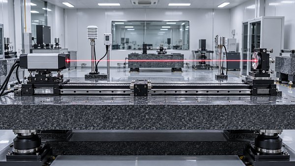
Most laser interferometer systems measure distance through air. The refractive index of air changes with temperature, pressure, humidity, and gas composition. Those changes alter the effective wavelength along the beam path. Environmental compensation can reduce the associated error, but it does not make the physical environment irrelevant.
The limiting case appears when environmental variation over the path produces apparent displacement comparable to the motion error or dimensional change under investigation. A machine axis may appear to drift even if its mechanical position is unchanged, or a real displacement may be assigned the wrong magnitude because the scale factor is based on unrepresentative environmental measurements.
A single ambient sensor is not necessarily adequate for a long beam path, a path crossing thermal gradients, or an enclosure with changing airflow. Local heating from motors, lamps, electronics, operators, process equipment, and air-handling systems can create non-uniform conditions. The result is especially problematic where the laser path and the machine or part occupy different thermal environments.
Vacuum operation, sealed paths, and highly controlled enclosures change the problem rather than eliminating it. They may reduce air-related uncertainty but elevate other factors, including window behavior, optical alignment stability, structural distortion, and the need to establish suitable traceability for the operating configuration.
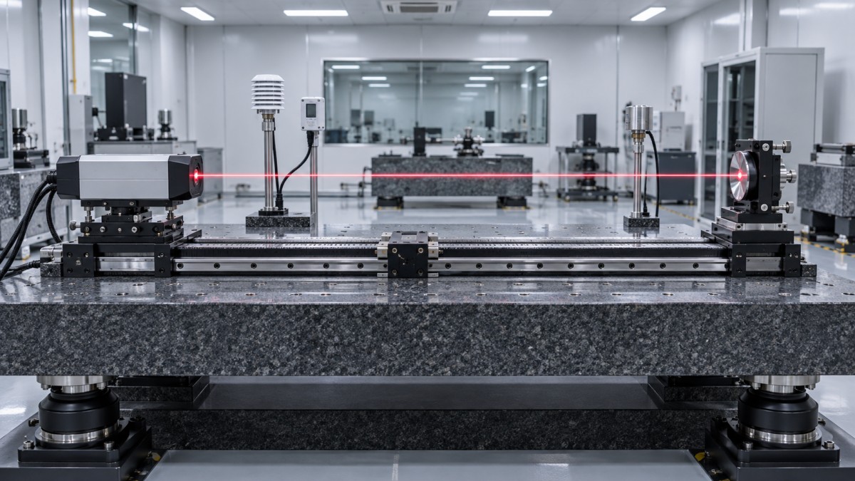
3. The beam does not represent the functional axis of motion
Even a highly stable laser scale cannot correct an improperly represented measurement geometry. Abbe offset is a familiar example: when the measurement axis is separated from the point of interest, angular motion produces a linear error at that point. An interferometer may report excellent positioning along its beam line while a tool center point, probe tip, wafer chuck, or inspection feature moves differently.
Cosine error has a related effect. If the laser beam is not collinear with the intended direction of travel, the measured displacement is a projection of the true motion. At small angles the numerical error can seem negligible, but it becomes consequential over long travel or under sub-micron requirements. Alignment quality also changes over time as mounts settle, structures heat, and equipment is serviced.
For multi-axis systems, the question becomes broader than one beam's axial accuracy. Straightness, pitch, yaw, roll, squareness, and dynamic following error can dominate the functional position uncertainty. An axial interferometer is indispensable for characterizing motion, yet it cannot by itself certify volumetric performance.
4. The target or reflector is not behaving as an ideal measurement object
Retroreflectors, plane mirrors, and other target arrangements have their own practical limits. Target tilt, mounting stress, surface quality, optical return strength, polarization effects, and changes in beam incidence may affect signal quality or introduce measurement artifacts. In scanning or high-speed motion, signal interruptions and servo-induced dynamics can matter as much as static optical accuracy.
A reflected beam that remains detectable is not automatically a reliable beam. Evaluators should ask how the system identifies loss of signal, cycle ambiguity, dropouts, or transient data corruption, and whether the software preserves sufficient diagnostic information to distinguish a measurement error from actual stage motion.
The Interferometer May Be Better Than the System Around It
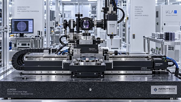
Many procurement errors stem from buying precision where the surrounding mechanics cannot use it. A laser interferometer with strong intrinsic performance does not overcome a granite structure with a thermal gradient, a flexible mounting bridge, a stage with variable friction, or a controller whose position feedback and commanded motion are poorly synchronized.
This is especially relevant when the interferometer is used as an external verification device rather than as the machine's primary feedback sensor. If the system measures position at one point while processing occurs at another, the evaluation must account for structural loop closure. The metrology loop should include the components that physically determine the functional dimension. Otherwise, the reported position may be internally consistent but operationally misleading.
Time also matters. A system can be repeatable during a short sequence and still fail to maintain accuracy across a shift, a thermal cycle, a maintenance interval, or a change in payload. Drift testing should therefore be tied to the real decision interval. An instrument that passes a five-minute repeatability demonstration may be inadequate for an eight-hour setup qualification or a tool-to-tool comparison conducted days apart.
For systems that combine laser data with encoders, cameras, capacitance probes, force sensors, or coordinate-measuring probes, synchronization requires equal attention. Each sensor can be accurate in isolation while the fused result is wrong because timestamps, coordinate frames, thermal states, or transformation assumptions are inconsistent.
How to Evaluate the Limiting Effect Before Purchase or Acceptance
A credible evaluation starts from the measurement task, not from a catalogue accuracy figure. Define the feature, axis, working volume, travel speed, thermal state, environmental envelope, and required decision uncertainty. Then ask what physical quantity the interferometer will actually observe and what transformations are required to obtain the desired result.
The following review points usually expose whether laser interferometer precision is sufficient in the intended system:
- Measurement range and path layout: Is the specified performance applicable to the full optical path, including folds, windows, and installed alignment geometry?
- Environmental model: How are temperature, pressure, humidity, and material expansion measured and applied? Are sensors located where their readings represent the beam path and the workpiece or machine structure?
- Uncertainty budget: Does it distinguish instrument performance from alignment, environmental, mechanical, target, and software contributions?
- Functional point: Is displacement measured at the point where dimensional performance matters, or is an Abbe-related correction required?
- Dynamic behavior: Does the test include the relevant acceleration, velocity, direction reversal, payload, and servo condition?
- Traceability and procedure: Can calibration and verification be linked to a documented procedure with defined environmental and setup conditions?
- Failure handling: Does the acquisition system flag signal loss, invalid compensation inputs, saturation, and interrupted measurement sequences?
Acceptance testing should include more than a single favorable run. Repeated measurements in both directions, after thermal stabilization and during representative operating conditions, give a more informative view of the practical limit. Where the system will support conformance decisions, the test plan should also consider readings near the relevant specification boundary rather than only nominal motion positions.
Standards Support Discipline, but They Do Not Substitute for an Application Model
Standards and established calibration practices provide important structure for terminology, traceability, environmental control, uncertainty evaluation, and machine-performance testing. They help prevent a supplier and buyer from using the same word, such as “accuracy,” to mean different things. Yet compliance with a general procedure does not establish suitability for every application.
A machine-axis verification may demonstrate axial positioning performance under a defined setup. It may not establish the uncertainty of a component feature measured under process load. Likewise, a traceable interferometer calibration supports confidence in the instrument scale but does not validate the geometry, thermal compensation, or data reduction used in a particular installed system.
Technical evaluators should therefore request the conditions behind each quoted result: travel range, mounting arrangement, compensation method, warm-up state, directionality, averaging, environmental limits, and uncertainty expression. A number without those conditions is difficult to compare and dangerous to place directly into a system specification.
Deciding What to Improve
When interferometer precision is found to limit the system, replacing the laser head is only one possible response. The more effective action may be a shorter or protected beam path, improved environmental sensing, better thermal isolation, revised optical geometry, relocation of the measurement axis, stiffer mounting, or an updated uncertainty model. In some cases, reducing the required uncertainty through a better-defined datum strategy or a more appropriate measurement method is more defensible than pursuing ever-smaller display increments.
The correct investment follows the dominant error source. If air-path variation is largest, a higher-resolution readout changes little. If Abbe error dominates, optical alignment and structural design deserve priority. If the laser scale itself is the largest contributor after the rest of the system has been controlled, then a different interferometer configuration, improved wavelength reference, or a more suitable measurement architecture becomes justified.
Laser interferometer precision limits a metrology system at the point where optical measurement uncertainty can no longer be treated as background noise. Identifying that point requires a system-level view: the beam path, the environment, the functional measurement axis, the mechanics, and the final decision all belong in the same evaluation.
Recent Articles
 2026.10.08How to assess measurement uncertainty from a precision metrology supplierPrecision metrology supplier guide: assess measurement uncertainty, traceability, environmental effects, calibration, and decision rules for reliable results.
 2026.10.07Metrology application notes for choosing CMM probe strategiesMetrology application notes for selecting CMM probe strategies, improving accuracy, access, repeatability, and confidence in complex feature inspection.
 2026.10.06What refresh rate do VR headsets need to reduce motion sicknessVR headsets need at least 90Hz to help reduce motion sickness. Discover why stable frame rates, low latency, and 120Hz support can deliver smoother, more comfortable VR experiences.
 2026.10.05What drives nano-indentation systems cost for a new lab?Nano-indentation systems cost: discover the real budget drivers for a new lab, from configuration and site readiness to software, calibration, and service.
 2026.10.04When does a micro fluidic probe OEM need custom channel geometry?Micro fluidic probe OEM guide: learn when custom channel geometry improves confinement, shear control, reagent savings, and process reliability.
 2026.10.03How to prevent cross-contamination in semiconductor gas handlingSemiconductor Gas Handling best practices to prevent cross-contamination, protect gas purity, improve process stability, and strengthen fab safety.
 2026.10.02How healthcare engineering improves the accuracy of diagnostic equipmentHealthcare engineering improves diagnostic accuracy through precision design, calibration, fluid control, and traceable validation for reliable clinical results.
 2026.10.01When does a steel-frame vibration isolation table provide enough stability?Vibration isolation table steel frame stability explained: assess stiffness, resonance, payload, and isolator performance for precise, reliable measurements.
 2026.09.30How probe station procurement alerts prevent costly supply delaysProbe station procurement alerts help teams spot configuration risks, lead-time changes, and compliance issues early—protecting test schedules and avoiding costly supply delays.
 2026.09.29Factory-Price Photoresist Chemicals: What Buyers Should Verify Before OrderingFactory price photoresist chemicals: learn the essential checks for process fit, lot control, purity, packaging, and total cost before ordering.
 2026.09.29When Does Laser Interferometer Precision Limit a Metrology System?Laser interferometer precision: learn when it limits metrology systems, from air-path effects and alignment errors to uncertainty budgets and smarter upgrades.
 2026.09.29Selecting a Semi-Automatic Wafer Prober for Low-Volume Test LinesChoose a semi automatic wafer prober for low-volume test lines with guidance on contact stability, flexible wafer handling, probe compatibility, and repeatable workflows.
 2026.09.29Piezo Valves for Fast Gas Dosing: Matching Response Time to Process NeedsPiezo valves for fast gas dosing: learn how to match response time, pressure conditions, and system design for stable, repeatable process control.
 2026.09.29Why a Piezo Valve Loses Repeatability—and How to Diagnose ItPiezo valve repeatability issues? Learn how to diagnose drive signals, contamination, pressure instability, bubbles, and wear before costly replacement.
 2026.09.29Nanopositioning Stages: Comparing Direct-Drive and Piezo-Flexure DesignsNanopositioning stages compared: explore direct-drive and piezo-flexure designs for travel, stiffness, settling time, thermal stability, and precision control.
 2026.09.29ArF Photoresist in Vietnam: Supply-Chain Risks for Semiconductor FabsArF photoresist in Vietnam: uncover supply-chain, compliance, logistics, and qualification risks. Build resilient sourcing strategies for semiconductor fabs.
 2026.09.29Ultra-Pure Silane Gas in the Middle East: Purity and Delivery ChecksUltra-pure silane gas Middle East acceptance guide: verify purity, CoA traceability, cylinder integrity, and safe delivery controls for critical processes.
 2026.09.29How high stability optical tweezers reduce drift in long experimentsOptical tweezers high stability systems reduce long-experiment drift through rigid mechanics, thermal control, low-noise optics, and meaningful feedback. Explore evaluation methods.
 2026.09.28How piezo polymer materials affect sensitivity in flexible sensorsPiezo polymer materials shape flexible sensor sensitivity. Explore stress transfer, film stability, electronics, and testing insights for reliable high-performance designs.
 2026.09.27When does recyclable skincare packaging justify its higher unit cost?Skincarepackaging costs more only when it protects formulas, supports credible recycling claims, reduces compliance risk, and delivers measurable commercial value.
 2026.09.26How to choose a hiking backpack that fits your torso lengthHikingbackpacks fitting guide: measure your torso, adjust hip belts and straps, and choose a stable, comfortable pack for every trail adventure.
 2026.09.25Which ISO standards apply to precision-engineered medical devices?ISO standards for precision engineering medical devices: explore ISO 13485, ISO 14971, metrology, biocompatibility, sterilization, and packaging requirements.
 2026.09.24How to choose athletic clothing that stays comfortable in humid weatherAthletic clothing for humid weather: learn how to choose breathable fabrics, low-chafe fits, and quick-drying layers for more comfortable workouts.
 2026.09.23How sheet metal welding choices affect dimensional accuracySheet metal welding choices shape dimensional accuracy. Explore heat input, joint design, fixturing, and inspection strategies to reduce distortion and improve repeatability.
 2026.09.22How specification preparation prevents flow-control errors in process systemsSpecification preparation for process systems prevents flow-control errors by defining operating ranges, pressure budgets, accuracy, materials, and control requirements before equipment selection.
 2026.09.21How to assess a German mass flow controller supplier for cleanroom useIndustrial & Manufacturing equipment supplier in Germany: assess cleanroom MFC partners for gas compatibility, leak integrity, calibration traceability, and lifecycle service.
 2026.09.20How to assess aerospace component manufacturing services for tight tolerancesAerospace component manufacturing services: learn how to verify tight-tolerance capability through metrology, process control, special-process oversight, and traceability.
 2026.09.19When does polycarbonate roofing need UV protection on both sides?Polycarbonateroofing: learn when dual-sided UV protection prevents yellowing, installation errors, and reflected-light damage in demanding roof designs.
 2026.09.18When high precision coordinate measuring machines justify tighter tolerancesHigh precision coordinate measuring machines justify tighter tolerances when uncertainty, process capability, and traceability protect critical performance. Explore smarter decisions.
 2026.09.17How can retailers verify safety before buying Montessori toys wholesale?Montessoritoyswholesale safety guide: verify SKU-specific tests, labels, traceability and market compliance before ordering.
 2026.09.16How to assess surgical instruments for reliable sterilizationAssess surgical instruments for reliable sterilization with practical guidance on cleanability, material compatibility, inspection, and validated reprocessing.
 2026.09.15How material science for food ingredients improves shelf stabilityMaterial Science for food ingredients reveals how moisture control, encapsulation, oxidation management, and smart packaging extend shelf life and protect quality.
 2026.09.14What purity specification do laboratory gases need for trace analysis?Ultra-high purity gases for laboratory use: learn how to specify, verify, and control critical impurities for reliable trace analysis and lower backgrounds.
 2026.09.13How to verify a lubricants exporter’s product quality before orderingLearn how to verify a lubricants exporter before ordering—from batch CoAs and lab tests to traceability, packaging, and export compliance. Reduce equipment and shipment risks.




















FILTER_CORE
REF_NO: 0042
Editors' Picks