How Sheet Metal Welding Choices Affect Dimensional Accuracy
Sheet metal welding choices directly influence dimensional accuracy, residual stress, distortion control, and inspection outcomes. For technical evaluators, process selection must begin with tolerance risk, not nominal welding speed.
The central conclusion is straightforward: lower, more controlled, and more repeatable heat input generally improves dimensional stability, but only when joint design, tooling, sequencing, and measurement strategy support it.
A fast welding process can still produce inaccurate assemblies when heat is poorly distributed, clamps permit movement, or inspection only occurs after irreversible distortion has developed.
What Technical Evaluators Should Assess Before Selecting a Welding Process
The search intent behind sheet metal welding and dimensional accuracy is usually practical: evaluators need to predict whether a fabrication route can repeatedly meet drawing tolerances after welding.
They are rarely seeking a generic comparison of TIG, MIG, laser, and resistance welding. They need evidence connecting process variables to measurable flatness, position, angularity, and profile outcomes.
The most important starting point is identifying critical-to-quality dimensions before welding begins. These may include datum relationships, hole location, flange angle, flatness, concentricity, or sealing-surface profile.
Dimensions that are easily corrected by machining require a different welding strategy than thin-wall features, enclosed assemblies, cosmetic surfaces, or components with inaccessible reference faces.
Technical reviewers should also distinguish local weld accuracy from final assembly accuracy. A visually sound weld can still shift critical interfaces enough to create fit-up failures downstream.
Material thickness matters because thin sheets heat rapidly and lose stiffness quickly. A 0.8-millimeter stainless panel responds very differently from a 4-millimeter structural steel bracket.
Production volume changes the decision as well. A manually controlled process may be acceptable for prototypes, while repeatable automated welding becomes necessary for tolerance-sensitive production assemblies.
The most useful evaluation question is not which process is universally precise. It is which process produces the lowest predictable dimensional variation for the specified geometry and manufacturing volume.
Heat Input Is the Primary Driver of Welding Distortion
During sheet metal welding, the weld zone expands while heated and contracts during cooling. Surrounding colder material resists that movement, creating residual stress and permanent geometric change.
Excessive heat input increases the size of the heat-affected zone, widens thermal gradients, and raises the likelihood of bowing, buckling, angular distortion, and longitudinal shrinkage.
Heat input is commonly approximated from voltage, current, travel speed, and process efficiency. Although simplified, this relationship helps evaluators compare potential thermal effects across welding methods.
Slower travel speed usually deposits more energy per unit length. This can improve fusion margins but often increases shrinkage, especially along long seams in thin sheet assemblies.
High heat input does not automatically mean poor quality. Certain joints require adequate penetration, but the objective is to achieve required fusion without unnecessary thermal loading.
TIG welding offers excellent arc control and clean weld appearance, yet its slower travel speed can make it distortion-prone when operators use extended dwell time or oversized weld beads.
MIG welding generally provides higher deposition rates than TIG. However, uncontrolled settings, large fillets, and inconsistent torch travel can introduce significant heat variation between individual assemblies.
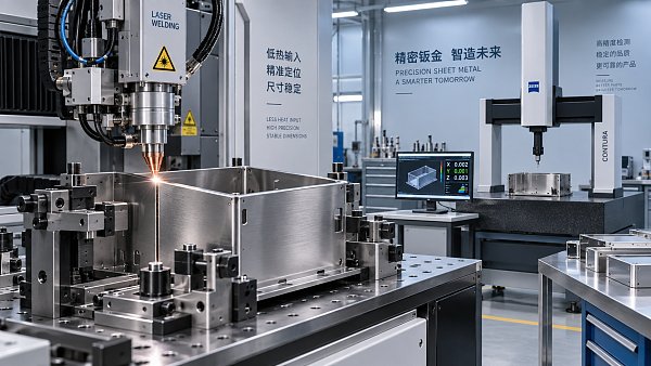
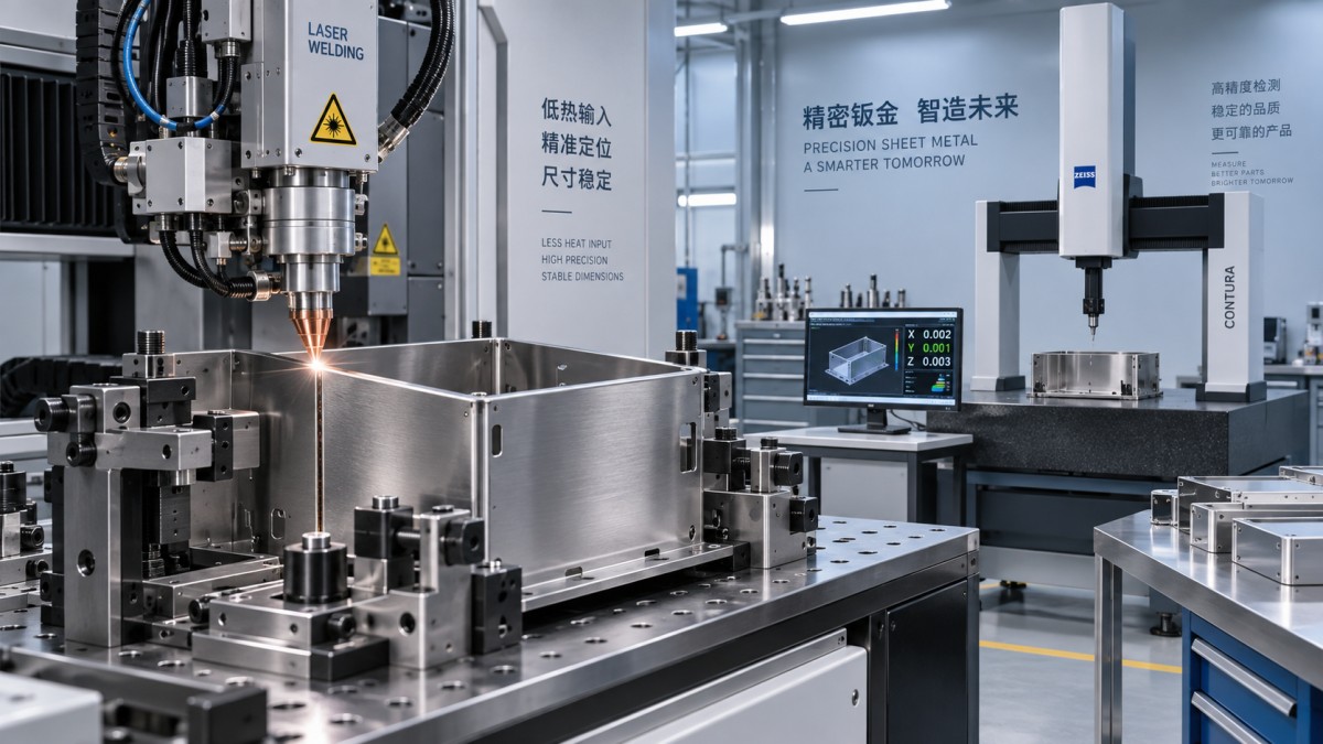
Laser welding concentrates energy into a small area and normally minimizes total heat input. Its dimensional advantages depend on precise joint fit-up, stable focus, and reliable fixture positioning.
Resistance spot welding applies heat locally and rapidly, often preserving overall panel shape better than continuous fusion welding. Electrode force, current balance, and weld spacing remain critical variables.
How Common Welding Processes Compare for Precision-Critical Sheet Metal Work
TIG welding is often selected for thin stainless steel, aluminum, and visible fabrication because it gives operators fine control over the weld pool and filler addition.
For dimensional accuracy, TIG performs best on short seams, tightly controlled joints, and low-volume work where skilled operators can use intermittent welding and carefully planned sequencing.
Its limitations emerge on long seams or heat-sensitive panels. Repeated manual starts, stops, and variable travel speeds can create inconsistent shrinkage patterns across nominally identical components.
MIG welding suits thicker sheet and larger fabricated structures where productivity matters. It can achieve acceptable accuracy, but tolerance-sensitive designs require disciplined parameter control and minimized weld volume.
Pulse MIG can reduce average heat input and improve control compared with conventional transfer modes. It is useful when productivity must increase without accepting broad thermal distortion.
Laser welding is often the strongest option for narrow seams, small precision housings, battery enclosures, sensor assemblies, and production parts with demanding post-weld dimensional requirements.
Its narrow weld profile reduces distortion, but laser welding transfers more risk upstream. Gap variation, contaminated edges, poor alignment, or unstable part presentation can quickly compromise quality.
Resistance spot welding is highly effective for overlapping sheet joints in automotive, appliance, electronics, and enclosure manufacturing. It avoids continuous seam shrinkage and supports fast automated production.
However, spot welding can create local indentation, electrode marks, and panel deformation. Evaluators must consider cosmetic requirements, electrode access, weld nugget consistency, and structural load paths.
Joint Design Often Determines Accuracy More Than the Welding Machine
Joint geometry controls restraint, weld volume, access, and heat flow. Selecting an advanced welding system cannot fully compensate for a joint that concentrates heat into flexible sheet features.
Butt joints usually offer better dimensional predictability than large lap joints when flatness matters. They reduce stacked material thickness and can limit eccentric shrinkage forces.
Lap joints are convenient for fabrication and resistance welding, but they may pull panels unevenly as the weld cools. Unequal stiffness can create angular movement near the overlap.
Fillet welds should be sized for the actual load requirement. Oversized fillets add unnecessary filler metal, increase heat input, and frequently create larger-than-expected angular distortion.
Intermittent welds reduce total heat and can improve flatness when sealing requirements permit. Their length, spacing, and placement must still provide appropriate stiffness and fatigue performance.
Continuous welds may be necessary for pressure retention, fluid containment, electromagnetic shielding, or corrosion protection. In these cases, seam location and sequence become especially important.
Symmetrical joint design can help balance thermal forces. When welding is unavoidable on one side, compensating features or controlled counter-welds may be considered during process development.
Technical evaluators should ask suppliers for weld symbols, throat sizes, intermittent patterns, and sequence assumptions. These details reveal whether dimensional control has been designed into the assembly.
Fixturing and Welding Sequence Control Dimensional Repeatability
Fixtures do more than hold parts in position. They establish datums, resist movement, manage heat flow, and determine whether each component enters the welding process consistently.
A fixture should locate critical features from functional datums rather than convenient edges. Referencing an unstable cut edge can transfer upstream blanking variation into the final assembly.
Excessive clamping can conceal distortion during welding and release it afterward. The assembly may measure correctly in the fixture but spring beyond tolerance when unclamped.
Insufficient clamping creates the opposite problem. Parts can shift during tack welding, arc initiation, or thermal expansion, producing positional errors that cannot be corrected economically afterward.
Good fixture design balances restraint with realistic release behavior. Development trials should measure parts both while restrained and after cooling and removal from the fixture.
Tack weld placement is especially important in thin sheet metal welding. Tacks define the initial geometry, but large or poorly sequenced tacks can introduce distortion before final welding begins.
Backstep welding, skip welding, and balanced alternating sequences distribute heat rather than concentrating it progressively along one edge. These methods can substantially reduce accumulated shrinkage.
For automated cells, fixture repeatability, robotic path accuracy, part loading position, and clamp confirmation should be monitored together. Welding repeatability cannot exceed the repeatability of the full system.
Where tolerances are extremely tight, adaptive fixturing, in-process probing, or pre-weld vision alignment may be justified. These controls reduce variation before thermal effects are introduced.
Material Selection Changes the Distortion Risk
Different sheet materials respond to welding heat differently because thermal conductivity, expansion coefficient, yield strength, and phase behavior determine how stress develops and relaxes.
Aluminum conducts heat quickly and expands significantly. It often requires higher heat input for fusion, yet its high thermal expansion can produce substantial distortion after cooling.
Stainless steel has lower thermal conductivity than aluminum, concentrating heat near the weld. This can simplify local fusion but increases the risk of localized warping and discoloration.
Carbon steel is generally more forgiving, although thin-gauge panels remain vulnerable to buckling. Coating removal, contamination, and variable material thickness can affect process consistency.
Galvanized steel introduces additional concerns because zinc vapor can affect weld formation and porosity. Coating preparation must be controlled without creating inconsistent local material conditions.
High-strength steels may retain greater residual stress after welding, depending on alloy and heat cycle. Evaluators should consider whether welding changes mechanical properties near critical load-bearing features.
Material certification alone does not guarantee predictable welding behavior. Incoming flatness, temper variation, coating condition, and edge quality should be considered during supplier qualification.
When comparing quotations, material substitutions require careful review. A lower-cost alloy or alternate thickness may alter distortion behavior enough to invalidate a previously qualified welding process.
Inspection Strategy Must Verify the Condition That Matters
Dimensional inspection should be planned around the final functional condition, not simply around convenient measurements. Parts may change after cooling, unclamping, handling, coating, or stress relief.
For precision sheet metal assemblies, first-article inspection should establish baseline variation in flatness, hole position, profiles, angularity, and critical interface dimensions after complete processing.
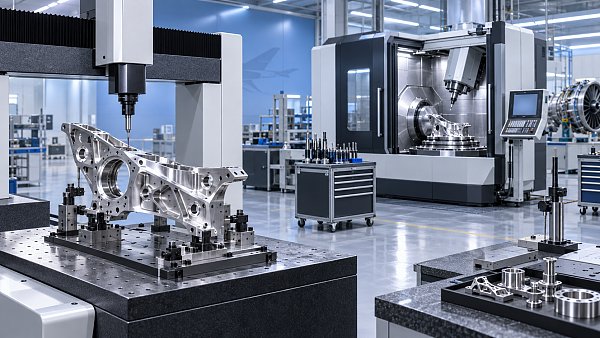
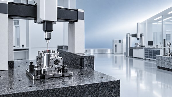
Coordinate measuring machines are valuable for complex datum relationships and geometric tolerances. Their usefulness depends on suitable probing access, measurement fixtures, and a validated inspection program.
Optical scanners and multi-sensor systems can quickly reveal broad panel distortion and local surface movement. They are particularly useful when welded assemblies have freeform or inaccessible features.
Simple gauges remain important for production control. Dedicated checking fixtures, go/no-go gauges, height gauges, and functional mating parts can detect drift faster than full laboratory inspection.
Measurement system analysis should not be overlooked. A process cannot be judged capable when gauge repeatability, fixture positioning, or operator method introduces uncertainty near the tolerance limit.
Inspecting only a finished sample can delay corrective action. In-process checks after tack welding, before final seams, and after unclamping help isolate where dimensional variation originates.
Statistical process control is most useful when linked to actionable variables. Tracking final flatness alone is less effective than correlating it with weld energy, clamp force, gap, and sequence.
A Practical Selection Framework for Dimensional Accuracy
Start by ranking dimensions according to functional consequence. Identify which deviations affect assembly fit, sealing, optical alignment, electrical contact, safety, or downstream automated handling.
Next, identify whether those dimensions are controlled before welding, during fixturing, or only after welding. This establishes where corrective action is technically possible and economically sensible.
Choose the lowest practical heat-input process that still meets penetration, strength, corrosion, appearance, and production-rate requirements. Avoid specifying a process solely from historical preference.
Review joint design and weld size before investing in expensive process controls. Reducing unnecessary weld volume often delivers larger accuracy gains than changing from one arc process to another.
Require representative weld trials using production-intent material, tooling, and sequence. Prototype trials performed with hand-fit samples rarely predict automated production dimensional capability reliably.
Define acceptance criteria for post-weld conditions, including cooling time, fixture release, finishing operations, and coating. Ambiguous inspection timing can create disputes between suppliers and buyers.
For high-risk assemblies, request capability data rather than isolated sample measurements. Process capability, repeatability studies, and control plans provide stronger evidence than a single conforming part.
Finally, evaluate total cost of quality. A faster welding method may be more expensive when it increases rework, distortion correction, inspection burden, scrap, or downstream assembly delays.
Conclusion: Welding Accuracy Is a System-Level Decision
Sheet metal welding choices affect dimensional accuracy through heat input, joint geometry, material response, fixturing, sequence control, and measurement discipline. No welding method is precise by default.
Laser and resistance welding can reduce thermal distortion in suitable applications, while TIG and MIG remain effective when weld volume, travel, and sequencing are tightly controlled.
For technical evaluators, the strongest decision is based on demonstrable post-weld capability. Specify critical dimensions early, validate the full process, and measure assemblies in their real functional condition.
When welding strategy is treated as part of the dimensional-control system rather than an isolated joining operation, fabrication teams can achieve better repeatability, lower correction costs, and more reliable assemblies.