
Microdynamics in Precision Motion: What Engineers Need to Measure
Nanometer-scale positioning performance is rarely determined by encoder resolution alone. A stage can display sub-nanometer command increments, a high-resolution interferometer can report apparently stable position, and a controller can meet a nominal bandwidth target—yet the assembled system may still miss its process window because of residual vibration, structural deformation, friction-induced motion, or unstable servo behavior.
Microdynamics is the set of small-amplitude, time-dependent mechanical and control effects that shape motion around the commanded position. It matters most where settling time, overlay, focus, alignment, scanning uniformity, or repeatable contact force cannot tolerate a transient that is insignificant at millimeter scale. The practical question is not whether a platform moves accurately under ideal conditions. It is whether it reaches, holds, and repeats the required state under the load, cable routing, thermal condition, trajectory, and disturbance environment of the intended machine.
Static accuracy is necessary, but it does not describe motion quality
Technical specifications commonly separate positioning accuracy, repeatability, resolution, and maximum speed. These values remain useful, but they do not fully describe how a system behaves during a move. A linear stage may have excellent bidirectional repeatability measured after a long dwell while showing substantial overshoot, ringing, or direction-dependent settling during a short point-to-point move. Those transient errors can be the dominant source of process variation.
The distinction is especially important when the process itself is dynamic. A wafer alignment stage, laser machining platform, optical inspection axis, probe-positioning system, or micro-assembly mechanism often has to achieve stable position within a finite time budget. The relevant error is then not merely the final error at the end of a test, but the maximum deviation and residual motion throughout the usable process interval.
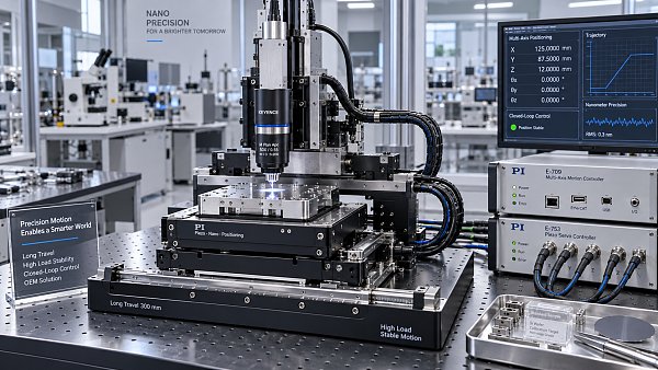
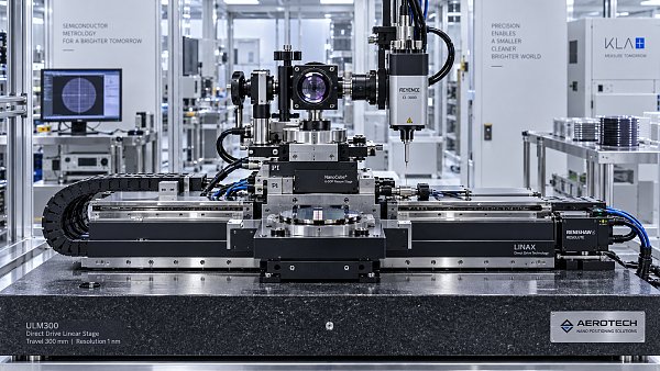
Microdynamics should therefore be evaluated as a system property. The moving platform, bearings, drive, encoder, cable chain, payload, base structure, isolation system, controller, and measurement instrument all contribute. Testing a bare stage can establish a useful baseline, but it cannot validate installed performance when the final payload changes mass distribution, center of gravity, cable stiffness, or structural modes.
Modal behavior: identify the frequencies that limit usable bandwidth
Every motion structure has resonant modes. At resonance, a relatively small force can produce amplified displacement, rotation, or deformation. In precision systems, the relevant modes are not limited to the main axis of travel. Pitch, yaw, roll, lateral bending, torsion, bearing-carriage deformation, and fixture compliance may couple into the process measurement even when translational encoder data appears acceptable.
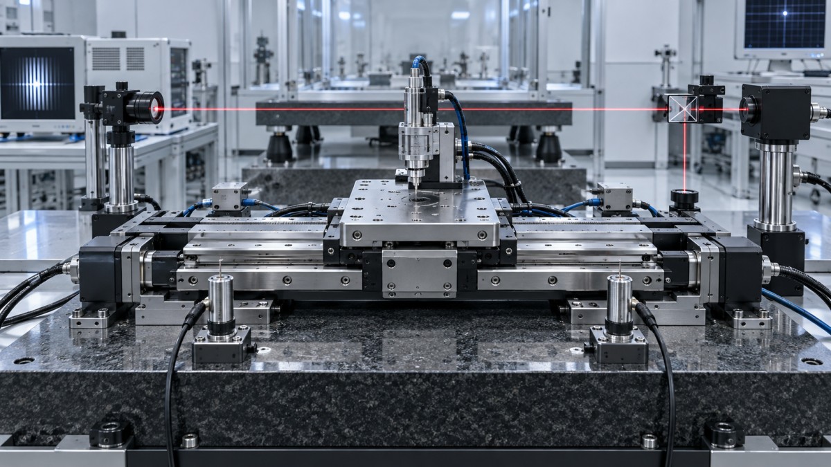
A frequency-response measurement is the most direct way to expose these limits. Depending on the system and access conditions, engineers may use swept-sine excitation, random excitation, impact testing, or controller-based identification. The output can be measured with accelerometers, laser Doppler vibrometry, interferometry, capacitive probes, strain sensors, or high-bandwidth encoder signals. No single sensor is sufficient for every mode: an encoder measures relative motion along its measurement axis, while an accelerometer may reveal structural vibration that does not appear directly in encoder feedback.
The important output is not simply the first resonance frequency. Engineers need to know the mode shape, damping, participation under the intended drive direction, and sensitivity to payload. A mode that is weakly excited in an unloaded test can become dominant when a tool head is mounted off-center. Similarly, a cable bundle can introduce a position-dependent stiffness change that shifts a resonance or creates different behavior at opposite ends of travel.
Control-loop bandwidth must be set with these resonances in mind. Raising gain to improve tracking can reduce low-frequency following error, but it also reduces stability margin when the loop approaches flexible modes. A high nominal servo bandwidth is not automatically beneficial if it produces amplified settling tails or sensitivity to small disturbances. The useful bandwidth is the bandwidth that remains robust across the operating envelope, not the highest value reached in a favorable laboratory configuration.
Settling time must be defined by the process window
“Settling time” is often reported without a sufficiently precise definition. A supplier may state that an axis settles within a specified number of milliseconds, but the number has limited value unless the move distance, payload, control condition, tolerance band, measurement point, and dwell criterion are known.
For a precision evaluation, settling should be measured from the actual process-relevant coordinate. If the process occurs at the end effector, measuring only motor position or carriage encoder position can hide angular or structural displacement at the working point. A long lever arm between the encoder line and the tool center point converts small pitch or yaw into meaningful linear error.
The settling criterion should also match the application. A tolerance band of ±100 nm and a tolerance band of ±5 nm describe entirely different machine capabilities. The measurement needs to confirm that the position remains inside the band for a defined hold period, rather than merely crossing it once. This distinguishes genuine stabilization from a decaying oscillation that happens briefly to pass through the target.
Move distance and direction must be part of the test matrix. Short moves may be limited by friction, quantization, and control reversal; longer moves may excite structural modes more strongly. Reversing direction may reveal asymmetry from cable forces, preload behavior, ball-screw effects, or actuator nonlinearity. Settling results should therefore be reviewed over representative move lengths, speeds, accelerations, positions in travel, and payload configurations.
Friction and force ripple are often hidden below nominal resolution
Microdynamics becomes particularly difficult near zero velocity. At this point, the difference between static friction and kinetic friction can create stick-slip motion: the drive force accumulates until it exceeds breakaway friction, the axis moves abruptly, and then the force balance changes again. The resulting displacement may be small in absolute terms but large relative to a nanometer-scale requirement.
Rolling-element guides, flexures, air bearings, crossed-roller bearings, and magnetic or voice-coil actuation each produce different low-speed behavior. None should be judged by a generic claim of “smooth motion.” The relevant evidence is a measured velocity and position trace at the intended creep speed, under the actual load and orientation. For vertical axes, gravitational loading and counterbalance behavior require separate attention. For rotary axes, torque ripple and bearing preload can introduce periodic position errors.
Drive architecture also matters. Cogging torque in permanent-magnet motors, current-loop noise, ball-screw lead variation, gear transmission errors, and commutation effects can appear as periodic disturbances. Their frequency changes with velocity, which means a system may perform well during static holding but generate repeatable contour error during scanning. Spectral analysis of following error and acceleration can help distinguish a structural resonance from a speed-related disturbance.
Tests near reversal deserve particular scrutiny. Bidirectional repeatability alone does not reveal the full issue because a system can return to the same average point while taking a different dynamic path on every reversal. Where the process involves scanning, rastering, contouring, or frequent short moves, evaluate following error, reversal spikes, and velocity stability continuously rather than relying only on point-to-point results.
Structural compliance determines where encoder feedback stops representing process position
Compliance is the displacement produced by force. In ultra-precision motion, it includes not only the stiffness of the stage body but also interfaces: mounting plates, granite or machine frames, vacuum fixtures, optical brackets, tool adapters, and payload clamps. A platform can have a high stiffness figure at the carriage while the combined assembly deflects at the point of use.
Static stiffness testing is valuable, but dynamic compliance is usually more revealing. A structure may resist a slowly applied force yet flex significantly under acceleration, changing process force, or ambient vibration. The frequency-response function between a disturbance input and the tool-center-point displacement provides a more realistic view of vulnerability.
Abbe error must be considered whenever the encoder measurement line is offset from the process point. If an axis experiences angular motion, the offset converts that angle into apparent linear displacement. The relationship is approximately linear for small angles: displacement error equals angular error multiplied by the offset distance. This is why a stage can meet a linear positioning specification while an optical head, probe tip, or deposition nozzle deviates from its intended location.
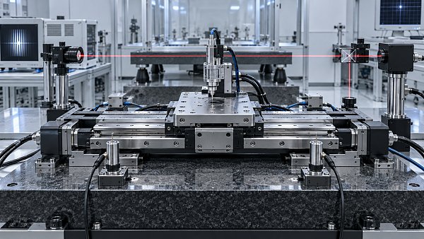
Metrology frame design is central to this problem. Where possible, the measurement system should reference the functional point directly or minimize the distance between the measurement axis and the process axis. When this is not feasible, angular errors need to be measured and compensated only if the behavior is repeatable and the compensation remains valid under operating conditions. Compensation cannot reliably correct random vibration, changing cable forces, or thermally evolving structure.
Control-loop response should be measured as a closed-loop system
Controller settings cannot be evaluated independently from mechanics. Proportional, integral, derivative, feedforward, notch filtering, friction compensation, and observer functions may improve one metric while worsening another. A notch filter can suppress a known mode, for example, but excessive filtering can introduce phase lag and reduce disturbance rejection elsewhere.
A meaningful servo assessment includes tracking error during representative trajectories, response to commanded steps, disturbance rejection, gain and phase margins where applicable, and sensitivity to changing inertia. For scanning applications, contour error and velocity ripple may be more relevant than step response. For pick-and-place or alignment operations, overshoot and in-position stability may dominate.
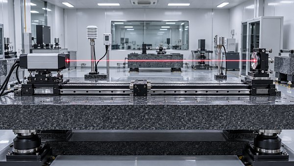
Encoder selection affects the interpretation of all these results. Incremental encoder resolution is not measurement accuracy. Interpolation error, cyclic error, electronic noise, reference mark behavior, mounting alignment, and thermal expansion of the scale can all affect feedback quality. Laser interferometers provide high displacement sensitivity and traceability advantages in many evaluation setups, but their readings are influenced by air refractive index unless environmental compensation or a vacuum path is used. Capacitive sensors can provide excellent local relative displacement measurement, although their usable range, target material, and mounting geometry require careful control.
A robust test uses independent measurement where possible. Measuring performance only with the feedback device inside the control loop risks confirming the controller’s own view of position rather than the actual motion of the process point. Independent metrology is particularly important when evaluating closed-loop correction claims.
Environmental and integration effects are part of the measurement, not test noise
Floor vibration, acoustic excitation, air turbulence, pressure fluctuations, thermal drift, electromagnetic interference, and utility-induced disturbances can dominate microdynamics in a completed machine. Excluding all external disturbances may be appropriate for component characterization, but it is insufficient for machine acceptance when the intended installation environment is known.
Thermal effects are often discussed separately from dynamics, yet the two interact. Motor heating can change bearing preload, cable stiffness, actuator constants, and structural geometry during operation. A stage that settles rapidly when cold may develop a different response after repeated high-acceleration moves. Measurement plans should distinguish short-term dynamic drift from longer thermal stabilization and should record the duty cycle that produced the result.
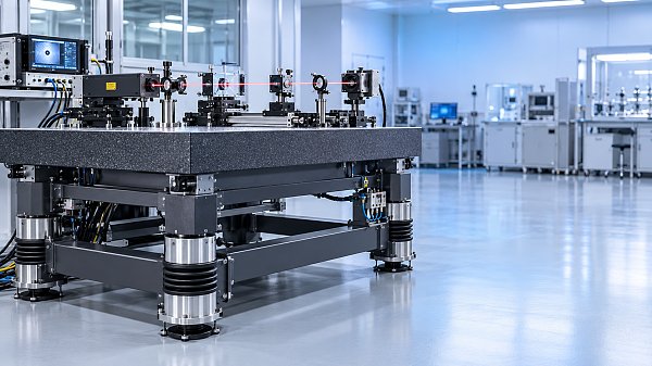
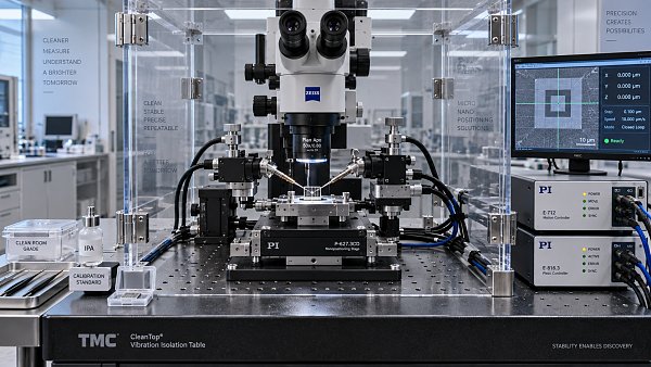
Isolation systems require similar caution. An isolation platform can reduce transmitted floor vibration above its effective isolation range but may introduce low-frequency motion near its natural frequency. The combined machine-isolator system must be assessed, particularly where long exposures, interferometric measurement, or low-frequency scanning are involved.
Standards provide a framework, not a complete microdynamics acceptance test
ISO 230 provides widely used test-method frameworks for machine tools. ISO 230-2 addresses positioning accuracy and repeatability of numerically controlled axes, while ISO 230-3 addresses thermal effects. These documents can support disciplined measurement practice, but they should not be treated as a complete validation method for every nano-positioning application. A machine can conform to a relevant positioning test procedure and still be unsuitable for a process with much tighter dynamic requirements.
The acceptance specification should translate the process need into measurable conditions: payload, orientation, travel range, trajectory, acceleration, process-point location, environmental state, allowed error band, and dwell duration. It should also state the metrology method, sampling bandwidth, filtering approach, coordinate reference, and uncertainty treatment. Without these conditions, comparisons between platforms may be technically valid in isolation but commercially misleading.
The most useful microdynamics evaluation is not a search for one headline number. It is a controlled map of how the motion system behaves at its limits: after a reversal, under a difficult payload, near a resonance, during a demanding scan, and after operating long enough for the machine to reach its real thermal state. That evidence shows whether nanometer-level performance is a repeatable operating capability or only a favorable specification point.
Recent Articles
 2026.10.10How to build a supplier capability evaluation scorecard for critical partsSupplier capability evaluation scorecard: build a risk-based framework with gates, evidence, and weighted criteria to qualify critical-part suppliers with confidence.
 2026.10.09When do sub micron pneumatic actuators improve metrology repeatability?Sub micron pneumatic actuators for metrology improve repeatability by reducing friction, controlling contact force, and accelerating settling time. Discover when they deliver measurable inspection gains.
 2026.10.08How to assess measurement uncertainty from a precision metrology supplierPrecision metrology supplier guide: assess measurement uncertainty, traceability, environmental effects, calibration, and decision rules for reliable results.
 2026.10.07Metrology application notes for choosing CMM probe strategiesMetrology application notes for selecting CMM probe strategies, improving accuracy, access, repeatability, and confidence in complex feature inspection.
 2026.10.06What refresh rate do VR headsets need to reduce motion sicknessVR headsets need at least 90Hz to help reduce motion sickness. Discover why stable frame rates, low latency, and 120Hz support can deliver smoother, more comfortable VR experiences.
 2026.10.05What drives nano-indentation systems cost for a new lab?Nano-indentation systems cost: discover the real budget drivers for a new lab, from configuration and site readiness to software, calibration, and service.
 2026.10.04When does a micro fluidic probe OEM need custom channel geometry?Micro fluidic probe OEM guide: learn when custom channel geometry improves confinement, shear control, reagent savings, and process reliability.
 2026.10.03How to prevent cross-contamination in semiconductor gas handlingSemiconductor Gas Handling best practices to prevent cross-contamination, protect gas purity, improve process stability, and strengthen fab safety.
 2026.10.02How healthcare engineering improves the accuracy of diagnostic equipmentHealthcare engineering improves diagnostic accuracy through precision design, calibration, fluid control, and traceable validation for reliable clinical results.
 2026.10.01When does a steel-frame vibration isolation table provide enough stability?Vibration isolation table steel frame stability explained: assess stiffness, resonance, payload, and isolator performance for precise, reliable measurements.
 2026.09.30How probe station procurement alerts prevent costly supply delaysProbe station procurement alerts help teams spot configuration risks, lead-time changes, and compliance issues early—protecting test schedules and avoiding costly supply delays.
 2026.09.29What Maintenance Does a Micro-Manipulation System Need?What maintenance does a micro-manipulation system need? Explore calibration, cleaning, motion checks, cable care, and environmental controls for reliable precision.
 2026.09.29Microdynamics in Precision Motion: What Engineers Need to MeasureMicrodynamics in precision motion: learn what engineers must measure to control vibration, settling, friction, compliance, and servo response for reliable nanometer-level results.
 2026.09.29OEM Nanopositioning Solutions: Specifying Travel, Load, and Control RequirementsOEM nanopositioning solutions guide: specify usable travel, real payload dynamics, feedback, and control integration for reliable precision instruments.
 2026.09.29Factory-Price Photoresist Chemicals: What Buyers Should Verify Before OrderingFactory price photoresist chemicals: learn the essential checks for process fit, lot control, purity, packaging, and total cost before ordering.
 2026.09.29When Does Laser Interferometer Precision Limit a Metrology System?Laser interferometer precision: learn when it limits metrology systems, from air-path effects and alignment errors to uncertainty budgets and smarter upgrades.
 2026.09.29Selecting a Semi-Automatic Wafer Prober for Low-Volume Test LinesChoose a semi automatic wafer prober for low-volume test lines with guidance on contact stability, flexible wafer handling, probe compatibility, and repeatable workflows.
 2026.09.29Piezo Valves for Fast Gas Dosing: Matching Response Time to Process NeedsPiezo valves for fast gas dosing: learn how to match response time, pressure conditions, and system design for stable, repeatable process control.
 2026.09.29Why a Piezo Valve Loses Repeatability—and How to Diagnose ItPiezo valve repeatability issues? Learn how to diagnose drive signals, contamination, pressure instability, bubbles, and wear before costly replacement.
 2026.09.29Nanopositioning Stages: Comparing Direct-Drive and Piezo-Flexure DesignsNanopositioning stages compared: explore direct-drive and piezo-flexure designs for travel, stiffness, settling time, thermal stability, and precision control.
 2026.09.29ArF Photoresist in Vietnam: Supply-Chain Risks for Semiconductor FabsArF photoresist in Vietnam: uncover supply-chain, compliance, logistics, and qualification risks. Build resilient sourcing strategies for semiconductor fabs.
 2026.09.29Ultra-Pure Silane Gas in the Middle East: Purity and Delivery ChecksUltra-pure silane gas Middle East acceptance guide: verify purity, CoA traceability, cylinder integrity, and safe delivery controls for critical processes.
 2026.09.29How Web Tension and Oven Zoning Affect Coating Calendering Line QualityCoating calendering line quality depends on stable web tension and precise oven zoning. Learn how to reduce gloss, gauge, adhesion, and embossing defects.
 2026.09.29How high stability optical tweezers reduce drift in long experimentsOptical tweezers high stability systems reduce long-experiment drift through rigid mechanics, thermal control, low-noise optics, and meaningful feedback. Explore evaluation methods.
 2026.09.28How piezo polymer materials affect sensitivity in flexible sensorsPiezo polymer materials shape flexible sensor sensitivity. Explore stress transfer, film stability, electronics, and testing insights for reliable high-performance designs.
 2026.09.27When does recyclable skincare packaging justify its higher unit cost?Skincarepackaging costs more only when it protects formulas, supports credible recycling claims, reduces compliance risk, and delivers measurable commercial value.
 2026.09.26How to choose a hiking backpack that fits your torso lengthHikingbackpacks fitting guide: measure your torso, adjust hip belts and straps, and choose a stable, comfortable pack for every trail adventure.
 2026.09.25Which ISO standards apply to precision-engineered medical devices?ISO standards for precision engineering medical devices: explore ISO 13485, ISO 14971, metrology, biocompatibility, sterilization, and packaging requirements.
 2026.09.24How to choose athletic clothing that stays comfortable in humid weatherAthletic clothing for humid weather: learn how to choose breathable fabrics, low-chafe fits, and quick-drying layers for more comfortable workouts.
 2026.09.23How sheet metal welding choices affect dimensional accuracySheet metal welding choices shape dimensional accuracy. Explore heat input, joint design, fixturing, and inspection strategies to reduce distortion and improve repeatability.
 2026.09.22How specification preparation prevents flow-control errors in process systemsSpecification preparation for process systems prevents flow-control errors by defining operating ranges, pressure budgets, accuracy, materials, and control requirements before equipment selection.
 2026.09.21How to assess a German mass flow controller supplier for cleanroom useIndustrial & Manufacturing equipment supplier in Germany: assess cleanroom MFC partners for gas compatibility, leak integrity, calibration traceability, and lifecycle service.
 2026.09.20How to assess aerospace component manufacturing services for tight tolerancesAerospace component manufacturing services: learn how to verify tight-tolerance capability through metrology, process control, special-process oversight, and traceability.
 2026.09.19When does polycarbonate roofing need UV protection on both sides?Polycarbonateroofing: learn when dual-sided UV protection prevents yellowing, installation errors, and reflected-light damage in demanding roof designs.



















FILTER_CORE
REF_NO: 0042
Editors' Picks
- 00
0000-00
How to build a supplier capability evaluation scorecard for critical parts - 00
0000-00
When do sub micron pneumatic actuators improve metrology repeatability? - 00
0000-00
How to assess measurement uncertainty from a precision metrology supplier - 00
0000-00
Metrology application notes for choosing CMM probe strategies