
What does measurement accuracy specified as % of full scale mean?
Measurement accuracy specified as ±0.5% of full scale usually means the stated error limit is calculated from the instrument’s full-scale reference value, regardless of the current reading. For a sensor with a 0–100 bar range, that gives an error limit of ±0.5 bar under the specified conditions. At a reading of 5 bar, the same ±0.5 bar represents 10% of the reading.
This is the practical consequence of full-scale accuracy: a percentage that looks small on a datasheet can become a large relative error near the bottom of the measurement range. To judge whether an instrument is suitable, convert its accuracy specification into engineering units, then compare that error with the tolerance required at your actual operating points.
How to calculate percentage-of-full-scale accuracy
When the manufacturer defines full scale as the measurement span, the calculation is:
Absolute error limit = accuracy percentage ÷ 100 × measurement span
For a 0–100 bar pressure sensor rated at ±0.5% FS:
Absolute error limit = 0.5 ÷ 100 × 100 bar = ±0.5 bar
The specification therefore describes an error band extending 0.5 bar in either direction. Its total width is 1 bar. It does not mean the sensor always has a 0.5 bar error, or that the error changes randomly across that entire band. The actual error may be smaller and may vary systematically with pressure, temperature, or measurement history.
To express that limit relative to a particular nonzero reading:
Equivalent percentage of reading = absolute error limit ÷ absolute reading × 100
At zero, percentage of reading is undefined because the calculation requires division by zero. The absolute error limit remains useful, which is one reason specifications based on span are convenient for instruments that measure close to zero.
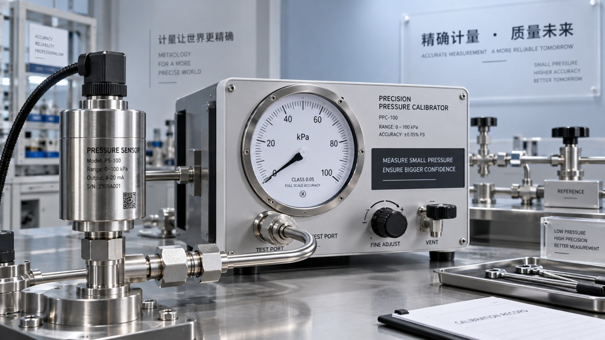
Full scale, span, and upper range value are not always interchangeable
For a zero-based range such as 0–100 bar, the upper range value and span are numerically identical. That makes the terminology easy to overlook. For an offset or bidirectional range, the distinction matters.
A range of −100 to +100 units has a span of 200 units, while its positive endpoint is +100 units. A specification calculated from the span produces twice the absolute error allowance of one calculated from the positive endpoint. The abbreviation “FS” alone may not establish which convention applies.
Look for the definition associated with the specification: full-scale output, full-scale range, span, rated capacity, or upper range limit. For an electrical output, “full-scale output” may refer to the output excursion corresponding to the measurement range. A 4–20 mA signal, for example, has a 16 mA output span.
The denominator is part of the specification. Two identical percentage values are comparable only when they use equivalent reference quantities and cover equivalent error components.
How full-scale accuracy differs from percentage-of-reading accuracy
A percentage-of-reading specification scales its error allowance with the measured value. A pure full-scale specification gives a fixed absolute allowance for a fixed range. Consider two hypothetical instruments measuring 10 bar:
- A 0–100 bar instrument rated at ±0.5% FS has an error limit of ±0.5 bar.
- An instrument rated at ±0.5% of reading has a percentage-based error term of ±0.05 bar at that point.
That comparison explains why percentage-of-reading performance can be attractive when measurements cover a wide operating range. However, the complete specification often includes a fixed term, such as a percentage of range, an offset, or a number of display counts.
For example, a hypothetical specification of ±(0.1% of reading + 0.02% of range), on a 100 V range at a 10 V reading, gives:
±(0.001 × 10 V + 0.0002 × 100 V) = ±0.03 V
The fixed range term becomes increasingly influential at low readings. Comparing only the percentage-of-reading term would understate the permitted error.
Specifications written as a sum normally require adding those terms as stated. They should not be combined using a statistical method merely because that gives a smaller result. Statistical combination belongs in an uncertainty analysis with justified assumptions about the contributing quantities.
What does the quoted “accuracy” actually include?
In formal metrology, measurement accuracy describes closeness to the true value; it is not itself a numerical quantity. Commercial datasheets nevertheless use “accuracy” as shorthand for a stated error limit or performance specification. The useful question is which effects that number covers.
A full-scale percentage might describe nonlinearity alone, a combination of nonlinearity and hysteresis, or a broader error band that also includes repeatability and other contributions. These are different claims.
- Nonlinearity describes departure from a specified reference line. The result depends partly on how that line is established.
- Hysteresis describes the difference in output at the same input depending on whether the input was approached from above or below.
- Repeatability describes agreement between repeated measurements under stated conditions.
- Zero and sensitivity errors shift the response or change its slope. Whether they are included depends on the specification.
A sensor can repeat closely while consistently reading high. Likewise, a low nonlinearity figure does not establish low total measurement error if zero offset, temperature effects, or drift are excluded.
Resolution is another separate property. A display may show increments of 0.01 bar while the instrument’s stated error limit is ±0.5 bar. Those extra digits help reveal changes, but they do not establish accuracy at the last displayed digit.
Conditions that can change the usable error limit
A quoted accuracy often applies under reference conditions. Operation outside those conditions may introduce additional error terms. Temperature is particularly relevant because it can shift both zero and sensitivity.
Distinguish the operating temperature range from the range over which a stated accuracy or compensated performance applies. Being able to function at a temperature does not necessarily mean the instrument retains its reference-condition error limit there.
Other relevant conditions include warm-up time, supply voltage, mounting orientation, vibration, and time since calibration. Their significance depends on the instrument. Pressure measurements can also be affected by installation height and connecting lines; electrical measurements by loading and lead resistance; dimensional measurements by alignment and thermal expansion.
Dynamic behavior needs a separate assessment. Static accuracy does not establish how well an instrument captures a fast pressure pulse or follows a moving stage. Response time, bandwidth, filtering, and sampling can affect the measured result even when the static specification is adequate.
The complete measurement chain matters too. A sensor connected to a transmitter, analog input, and scaling function acquires contributions from those stages. Digital communication removes some analog conversion steps, but it does not eliminate sensor error, installation effects, or drift.
Choosing a range from the allowable error
Range selection should begin with the process requirement. Identify the lowest important reading, the normal operating band, the maximum measurement input, and the error that the measurement task can tolerate.
For a purely full-scale specification, a useful preliminary relationship is:
Maximum permissible span = allowable absolute instrument error ÷ fractional full-scale specification
Suppose a hypothetical application allocates ±0.1 bar to the instrument’s specified error, and the candidate instrument is rated at ±0.5% of span. The largest span satisfying that allocation is:
0.1 bar ÷ 0.005 = 20 bar
A 0–20 bar version would therefore meet that particular allocation under the specification’s stated conditions. A 0–100 bar version with the same percentage rating would not.
This calculation is a screening tool. If ±0.1 bar is the allowance for the entire measurement system, allocating all of it to the sensor leaves no room for installation, acquisition, environmental, or other contributions.
A smaller range also has practical limits. It must cover the required measurements and accommodate the application’s pressure or input conditions. Overload survival does not imply valid measurement above the rated range. Where normal operation and occasional peaks are far apart, possible approaches include separate measurement ranges, appropriate protection, or an instrument with a suitable combined error specification.
Changing the displayed range may not improve accuracy
Rescaling a display or transmitter output does not automatically change the sensor’s underlying accuracy basis. A device with a wide sensing range may retain an error contribution tied to that original range after its output is configured for a narrower interval.
For configurable transmitters, distinguish the sensor’s range limit from the configured span. The specification may use either quantity or include terms involving both. A smaller configured span can therefore make a fixed sensor error larger as a percentage of the displayed range.
Autoranging instruments introduce another variation: selecting a lower hardware range may reduce a range-dependent error term, but the applicable formula still governs. Range changes can also affect resolution, settling behavior, and overload capability.
Use calibration evidence without confusing error and uncertainty
A datasheet error limit and calibration uncertainty answer different questions. The datasheet states performance under defined conditions. Calibration reports the instrument’s response at tested points, together with the uncertainty associated with those results.
A calibration correction can compensate for a measured systematic error, provided the correction remains applicable. It does not remove uncertainty in that correction, subsequent drift, hysteresis, or effects caused by different operating conditions.
When a measurement supports a pass/fail decision, its uncertainty also affects how confidently a result can be compared with a tolerance boundary. Any acceptance rule or guard band should be defined for that task; a universal accuracy ratio cannot replace that decision.
Before approving an instrument, translate the proposed specification into a requirement that can be checked. Record the range and denominator, calculate the error at the lowest important reading and normal operating points, identify included and excluded effects, and account for the measurement chain.
A useful requirement is more specific than “accuracy better than 0.5%.” It states the allowable error in engineering units over the required measurement interval, under the relevant temperature and installation conditions. That gives suppliers a clear target and makes competing specifications meaningfully comparable.
Taglist:
Recent Articles
 2026.10.16What does measurement accuracy specified as % of full scale mean?Understand measurement specification accuracy as % of full scale. Learn to calculate error, compare sensor ranges, and choose the right instrument with confidence.
 2026.10.15How temperature affects high-accuracy dimensional analysis systemsDiscover how temperature affects high accuracy dimensional analysis systems, and learn practical ways to control thermal drift, improve compensation, and verify measurement accuracy.
 2026.10.14How air pressure affects precision pneumatic actuator repeatabilityPrecision Pneumatic actuator repeatability depends on more than supply pressure. Discover how pressure, friction, and flow affect positioning—and how to improve consistency in your application.
 2026.10.13How to choose a packaging manufacturer for small production runsChoose a packaging manufacturer for small production runs with confidence. Discover how to compare costs, verify samples, and secure quality packaging without excess inventory.
 2026.10.12Qualifying an Ultra-Pure Silane Gas Manufacturer: Batch Consistency and TraceabilityQualify an ultra-pure silane gas manufacturer with confidence. Learn how to verify batch consistency, analytical results, and cylinder traceability to reduce sourcing risks.
 2026.10.12Choosing an Ultra-Pure Silane Gas Supplier: Lead Times, Delivery, and Backup SupplyChoose an ultra-pure silane gas supplier with reliable lead times, compliant delivery, and qualified backup supply. Learn what to verify to protect production and reduce supply risks.
 2026.10.12Ultra-Pure Chemicals in Latin America: What Shapes Regional Supply and Demand?Ultra-pure chemicals Latin America: explore demand drivers, qualified supply, and purity risks to uncover smarter sourcing and investment opportunities.
 2026.10.12What Materials Data Is Needed to Qualify a New PVD Target Supplier?Which material science data is essential before qualifying a new supplier? Discover PVD target checks for purity, microstructure, density and bond integrity to qualify suppliers with confidence.
 2026.10.12What Should a Private-Label Photoresist Quality Agreement Include?Build a stronger private label manufacturing quality agreement for photoresist. Discover essential clauses for specifications, batch release, change control, and traceability.
 2026.10.12How Much Does an Optical Tweezers System Cost?Explore optical tweezers system price ranges, key cost drivers, and ownership expenses. Compare configurations and learn how to choose the right setup for your research budget.
 2026.10.12How to size commercial refrigerators for a restaurant kitchenDiscover how commercialrefrigerators should be sized for peak demand, smarter workflow, food safety, and reliable restaurant kitchen performance.
 2026.10.11How procurement planning reduces supply risk in Latin AmericaProcurement planning Latin America helps reduce supply risk with supplier qualification, import readiness, inventory controls, and contingency sourcing.
 2026.10.10How to build a supplier capability evaluation scorecard for critical partsSupplier capability evaluation scorecard: build a risk-based framework with gates, evidence, and weighted criteria to qualify critical-part suppliers with confidence.
 2026.10.09When do sub micron pneumatic actuators improve metrology repeatability?Sub micron pneumatic actuators for metrology improve repeatability by reducing friction, controlling contact force, and accelerating settling time. Discover when they deliver measurable inspection gains.
 2026.10.08How to assess measurement uncertainty from a precision metrology supplierPrecision metrology supplier guide: assess measurement uncertainty, traceability, environmental effects, calibration, and decision rules for reliable results.
 2026.10.07Metrology application notes for choosing CMM probe strategiesMetrology application notes for selecting CMM probe strategies, improving accuracy, access, repeatability, and confidence in complex feature inspection.
 2026.10.06What refresh rate do VR headsets need to reduce motion sicknessVR headsets need at least 90Hz to help reduce motion sickness. Discover why stable frame rates, low latency, and 120Hz support can deliver smoother, more comfortable VR experiences.
 2026.10.05What drives nano-indentation systems cost for a new lab?Nano-indentation systems cost: discover the real budget drivers for a new lab, from configuration and site readiness to software, calibration, and service.
 2026.10.04When does a micro fluidic probe OEM need custom channel geometry?Micro fluidic probe OEM guide: learn when custom channel geometry improves confinement, shear control, reagent savings, and process reliability.
 2026.10.03How to prevent cross-contamination in semiconductor gas handlingSemiconductor Gas Handling best practices to prevent cross-contamination, protect gas purity, improve process stability, and strengthen fab safety.
 2026.10.02How healthcare engineering improves the accuracy of diagnostic equipmentHealthcare engineering improves diagnostic accuracy through precision design, calibration, fluid control, and traceable validation for reliable clinical results.
 2026.10.01When does a steel-frame vibration isolation table provide enough stability?Vibration isolation table steel frame stability explained: assess stiffness, resonance, payload, and isolator performance for precise, reliable measurements.
 2026.09.30How probe station procurement alerts prevent costly supply delaysProbe station procurement alerts help teams spot configuration risks, lead-time changes, and compliance issues early—protecting test schedules and avoiding costly supply delays.
 2026.09.29How Often Should a Laser Interferometer System Be Calibrated?How often should a laser-interferometer system be calibrated? Explore risk-based intervals, traceability, verification checks, and compliance tips for precision measurements.
 2026.09.29Is Private Label Manufacturing Suitable for Regulated Components?Is private label manufacturing suitable for regulated components? Explore traceability, quality controls, change management, and supplier qualification essentials.
 2026.09.29How Can Procurement Planning Reduce Single-Source Supply Risk?How can procurement planning reduce single-source supply risk? Discover practical strategies for qualifying alternatives, mapping dependencies, building buffers, and protecting critical operations.
 2026.09.29What Should a Precision Manufacturing Supplier Audit Include?What should be included in a precision manufacturing supplier audit? Explore essential checks for process capability, metrology, traceability, and risk control.
 2026.09.29How Do Export Controls Affect Semiconductor Equipment Lead Times?How do export controls affect semiconductor equipment lead times? Discover licensing, screening, supplier, and service risks—and plan smarter to protect fab schedules.
 2026.09.29What Maintenance Does a Micro-Manipulation System Need?What maintenance does a micro-manipulation system need? Explore calibration, cleaning, motion checks, cable care, and environmental controls for reliable precision.
 2026.09.29Microdynamics in Precision Motion: What Engineers Need to MeasureMicrodynamics in precision motion: learn what engineers must measure to control vibration, settling, friction, compliance, and servo response for reliable nanometer-level results.
 2026.09.29OEM Nanopositioning Solutions: Specifying Travel, Load, and Control RequirementsOEM nanopositioning solutions guide: specify usable travel, real payload dynamics, feedback, and control integration for reliable precision instruments.
 2026.09.29Factory-Price Photoresist Chemicals: What Buyers Should Verify Before OrderingFactory price photoresist chemicals: learn the essential checks for process fit, lot control, purity, packaging, and total cost before ordering.
 2026.09.29When Does Laser Interferometer Precision Limit a Metrology System?Laser interferometer precision: learn when it limits metrology systems, from air-path effects and alignment errors to uncertainty budgets and smarter upgrades.
 2026.09.29Selecting a Semi-Automatic Wafer Prober for Low-Volume Test LinesChoose a semi automatic wafer prober for low-volume test lines with guidance on contact stability, flexible wafer handling, probe compatibility, and repeatable workflows.

























FILTER_CORE
REF_NO: 0042
Editors' Picks