
Micro-Manipulation accuracy drops under repeated motion
When Micro-Manipulation accuracy drops under repeated motion, after-sales maintenance teams face more than routine wear—they confront hidden drift, unstable repeatability, and rising customer complaints. This article examines the mechanical, pneumatic, and control-system factors behind performance loss, helping service professionals identify root causes faster and restore ultra-precision systems with confidence.
Why repeated-motion accuracy loss must be judged by application scenario
In Micro-Manipulation systems, the same symptom can mean very different things depending on where the equipment is used. A pick-and-place unit in semiconductor packaging may fail because of thermal drift after 8 to 12 hours of continuous cycling, while a biological handling platform may show accuracy loss after frequent sterilization, humidity variation, or low-force tool replacement. For after-sales teams, the first task is not only to measure error, but to identify the operating scenario behind that error.
This matters because repeated motion creates layered degradation. Mechanical backlash, stage friction growth, air supply fluctuation, cable drag, encoder contamination, and controller tuning drift do not appear at the same rate. In some systems, repeatability may remain within ±1 µm during the first 20,000 cycles but expand to ±3 µm after 100,000 cycles. In higher-end nano-positioning environments, even a shift from 100 nm to 300 nm can be enough to trigger process rejection.
After-sales maintenance personnel also operate under business pressure. They are expected to shorten downtime, protect warranty margins, and avoid unnecessary part replacement. A scenario-based troubleshooting method helps separate actual hardware wear from installation, environment, or software compensation issues. This is especially important in cross-industry Micro-Manipulation applications where one maintenance checklist does not fit all production conditions.
Common business environments where repeated-motion drift appears
The table below helps service teams map the complaint to the most likely use case. This improves first-response accuracy and reduces the risk of replacing motors, valves, or stages before basic environmental and process conditions are verified.
This comparison shows why service teams should begin with workload profile, ambient conditions, and motion duty cycle. In practical field work, the same Micro-Manipulation complaint may be resolved by air quality correction in one plant and by servo retuning or stage replacement in another. Scenario awareness saves time during the first 30 to 60 minutes of diagnosis, when most costly wrong decisions are made.
Scenario 1: High-cycle electronics and semiconductor handling
In electronics packaging, wafer handling, probe positioning, and miniature component transfer, Micro-Manipulation systems often run in dense cycles with short travel distances. The challenge here is not peak load, but repeated micro-movement under constant thermal and dynamic stress. A stage that appears stable during manual commissioning can lose precision after 6 to 8 hours when actuator temperature rises by only a few degrees and causes slight dimensional expansion.
After-sales maintenance staff in this scenario should first check whether the loss is directional, cumulative, or random. Directional error usually points to backlash, screw wear, guide contamination, or preload change. Cumulative offset often suggests thermal drift or software compensation mismatch. Random scatter is more likely tied to electrical noise, unstable air supply in pneumatic assist modules, or encoder signal degradation. These distinctions reduce unnecessary disassembly.
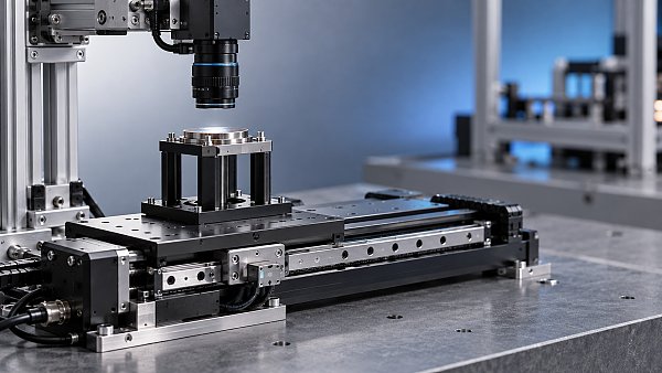
In high-cycle Micro-Manipulation, another overlooked factor is cable management. Repeated drag-chain flexing can introduce side load into small axes, especially on sub-micron systems with low-friction bearings. If error increases near stroke ends, the cable route, bend radius, and connector strain should be examined before replacing the motion platform.
What to inspect first in a 24/7 production cell
- Verify cycle count since last calibration or preventive service; many issues become visible after 500,000 to 2,000,000 motion events depending on stroke and load.
- Measure axis temperature at startup and after 2 hours, 4 hours, and 8 hours of operation to identify thermal growth trends.
- Check encoder signal quality, servo following error, and settling time against baseline values stored during acceptance testing.
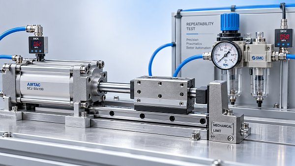
- Inspect pneumatic filters and regulator stability if air-assisted damping, gripping, or counterbalance functions are present.
A typical service mistake in this scenario is relying on static accuracy checks only. Static tests may pass even when dynamic repeatability is deteriorating. Run a repeated-motion test for 100, 500, or 1,000 cycles at production speed, and compare endpoint spread, settling time, and overshoot behavior. In many field cases, the customer complaint only appears under real duty conditions, not under slow maintenance mode.
Maintenance signals that should trigger deeper intervention
If repeatability worsens by more than 20% relative to historical baseline, or if positional correction values increase steadily over 2 to 4 service intervals, it is usually time to move beyond cleaning and recalibration. That pattern often indicates wear progression in guideways, couplings, ball screws, flexure elements, or feedback components. For high-value production lines, waiting for total failure can multiply downtime costs.

Scenario 2: Biomedical, laboratory, and low-force handling environments
In biomedical and laboratory automation, Micro-Manipulation systems often handle delicate samples, micro-tools, or implant-related components. Here, repeated motion accuracy loss may not come from heavy wear, but from subtle contamination, seal degradation, moisture variation, and force sensitivity. A system can still hit position coordinates while applying the wrong contact force, which creates quality issues that are easy to misread as operator error.
This scenario requires maintenance teams to pay closer attention to cleaning chemistry, sterilization routines, and enclosure conditions. Exposure to vapor, fine particulate, or aggressive cleaning agents can change friction characteristics in miniature bearings and seals over a period of 3 to 6 months. In piezo-based or flexure-based Micro-Manipulation, contamination can also affect fine-travel smoothness and lead to stick-slip behavior that only appears at low speed.
Another challenge is that biomedical users often prioritize gentle motion and sample safety over throughput. As a result, a customer may report “inconsistent placement” when the underlying problem is unstable settling, not absolute coordinate drift. Maintenance teams should therefore review motion profiles, acceleration ramps, and dwell timing rather than focusing only on axis calibration.
Scenario-specific checkpoints for low-force Micro-Manipulation
The following checklist is useful when service calls involve unstable handling, missed picks, variable contact, or drift after cleaning procedures. These conditions are common where motion amplitudes are small but precision tolerance remains tight.
- Confirm whether the issue began after sterilization, enclosure maintenance, tool exchange, or software update.
- Check humidity and temperature variation during one shift; a range change from 40% to 60% RH can affect some sensitive setups.
- Inspect gripper force consistency, vacuum response time, and pneumatic pulse stability where assisted handling is used.
- Review low-speed motion logs for stick-slip, dithering, or delayed settling that may not appear in coarse positioning tests.
In this environment, a good service practice is to create two verification standards: one for positional repeatability and one for functional handling quality. For example, a stage may still repeat within ±2 µm, yet contact force or grip timing may drift enough to affect usable output. That distinction is especially relevant in implant preparation, microscopy support, and miniature biological sample transfer.
Scenario 3: Optics, photonics, aerospace, and high-stability assembly
In optics alignment, photonics packaging, and aerospace micro-assembly, Micro-Manipulation errors often emerge during long settling periods or ultra-fine adjustment sequences rather than during fast travel. The customer may describe the machine as “still accurate at first move, but not stable enough to lock the final position.” This is a different service problem from high-cycle wear. It points more often to vibration coupling, thermal sensitivity, controller tuning, or mounting integrity.
These applications usually operate with tighter performance expectations, sometimes in the sub-micron or even nanometer-sensitive range. A floor vibration input that is harmless in general automation can become significant here. So can airflow, enclosure fan cycling, or nearby machine impulse. If Micro-Manipulation accuracy drops under repeated motion only during production hours and improves during quiet periods, the maintenance team should expand beyond the machine and inspect facility interaction.
Another common issue is compensation overuse. In an effort to maintain fine accuracy, some sites repeatedly adjust software parameters to mask mechanical change. Over several service visits, this can create unstable loops, increased settling time, and oscillatory micro-corrections. For after-sales professionals, it is important to compare current control values with original commissioning ranges and identify whether the machine is being “held together by compensation.”
Comparing root-cause emphasis across three major scenarios
This table summarizes how after-sales teams should prioritize inspection efforts depending on the business setting. It is especially useful for organizations supporting multiple sectors with shared service resources.
The main takeaway is that Micro-Manipulation service quality improves when maintenance teams classify the complaint by environment, duty pattern, and final process requirement. This reduces the risk of over-repair in sensitive systems and under-repair in high-cycle systems where wear is already progressing beyond acceptable limits.
How to adapt troubleshooting and service intervals by scenario
A strong after-sales process does not use one generic maintenance interval for all Micro-Manipulation equipment. Instead, service frequency should be linked to cycle count, contamination level, thermal load, and customer tolerance. In many industrial settings, inspection every 3 months is reasonable for high-duty systems, while lower-duty laboratory platforms may need a functional verification every 6 months but a cleaning and environmental review every 4 to 8 weeks.
Troubleshooting should also move in layers. Start with installation and environment, then check motion logs and control parameters, then inspect mechanical components, and only after that consider part replacement. This sequence is practical because a surprising percentage of field complaints come from air quality variation, fixture movement, or parameter drift rather than irreversible hardware failure. For service teams managing cost, this layered method protects both response time and parts budget.
Where available, baseline data is the most valuable service asset. Original acceptance values for repeatability, settling time, encoder noise, and axis temperature allow maintenance staff to identify whether the machine changed by 5%, 15%, or 40%. Without that comparison, teams are forced to rely on subjective judgments, which increases callback risk.
Recommended service approach by operating condition
The table below can be used as a practical planning guide for field service, spare preparation, and customer communication. It helps maintenance teams explain why Micro-Manipulation equipment in different conditions should not be maintained in the same way.
These intervals are not fixed rules, but they reflect common field logic. If the customer changes load, speed, shift pattern, or room condition, the service plan should change as well. For complex Micro-Manipulation installations, maintenance value comes from matching support actions to actual use profile rather than applying a single universal schedule.
Frequent misjudgments that increase callback rates
- Treating all repeatability problems as actuator wear without checking thermal or environmental influence.
- Recalibrating repeatedly without identifying the source of drift, which only delays deeper failure.
- Ignoring pneumatic support quality in systems where air pressure variation changes clamping, damping, or tool response.
- Using no-load service tests even though the customer problem occurs only under process load or real tool mass.
Reducing these misjudgments can improve first-time fix success and strengthen customer trust. In many cases, the customer is not asking for a textbook explanation of Micro-Manipulation physics. They want a service team that understands their application context and can restore reliable operation without trial-and-error replacement.
Why choose us for Micro-Manipulation support and what to discuss next
At G-UPE, we approach Micro-Manipulation issues from the full system perspective: mechanical transmission, pneumatic and fluid support, metrology feedback, environmental sensitivity, and application duty profile. That multidisciplinary view is important for after-sales maintenance teams because ultra-precision performance loss rarely comes from one isolated variable. It often sits at the intersection of motion hardware, control logic, facility condition, and process expectation.
If you are investigating accuracy drop under repeated motion, we can help you structure the problem faster. Useful discussion points include current repeatability range, cycle count, load condition, travel distance, shift pattern, air quality, thermal trend, calibration history, and whether the problem appears in static test, dynamic test, or final process result. We can also support parameter confirmation, application-oriented troubleshooting logic, maintenance interval planning, component selection guidance, and delivery-cycle discussion for replacement-critical parts.
Contact us if you need a more precise evaluation for your Micro-Manipulation scenario. You can consult on fault symptoms, system matching, service priorities, spare planning, custom solution direction, metrology checkpoints, standards-related concerns such as ISO, SEMI, or IEEE alignment, sample-support feasibility, and quotation communication. The clearer the application scenario, the faster the path to stable accuracy recovery.
Taglist:
Recent Articles
 2026.10.22Leadmicro Adds PVD Products, Expanding ALD, CVD and PVD CoverageLeadmicro expands ALD, CVD and PVD coverage with new iMagtron PVD products and a ruthenium ALD process. Explore what these advances mean for thin-film deposition and equipment buyers.
 2026.10.22What limits commercial adoption of micro-robotics in Latin America?Micro-robotics Latin America: What limits commercial adoption? Explore costs, integration hurdles, and service gaps—and learn how to reduce investment risks.
 2026.10.21NTT, Furukawa Electric and Partners Launch Photonics Mass-Production R&DExplore NTT and Furukawa Electric's photonics mass-production R&D with partners, targeting scalable chip manufacturing for energy-efficient AI computing and higher-bandwidth data centers.
 2026.10.21What ultra-precision engineering case studies reveal about thermal driftExplore ultra-precision engineering project cases to uncover hidden thermal drift, assess compensation, and learn what evidence to request before choosing a precision system.
 2026.10.20BASF Signs Letter of Intent with Taiwan Ministry to Expand Guanyin Semiconductor MaterialsBASF’s planned Guanyin semiconductor materials expansion targets sub-2nm manufacturing. Explore what its letter of intent with Taiwan’s Ministry of Economic Affairs could mean for chipmakers.
 2026.10.20How to estimate medical technology costs beyond the purchase priceEstimate medical technology cost beyond the purchase price. Uncover hidden expenses, compare lifecycle costs, and use this guide to make smarter procurement decisions.
 2026.10.1960 Minutes: Iran War Drives Global Helium Shortage, Threatening Semiconductor SupplyIran war-linked global helium shortage reportedly threatens semiconductor supply. Explore chipmaking risks and practical steps to verify inventories, shipments and supplier commitments.
 2026.10.19How to specify zinc coating weight for prepainted GI steel coilsSpecify zinc coating weight for prepainted gi steel coils with confidence. Learn how to define Z275, compare standards, and verify compliance to avoid costly purchasing mistakes.
 2026.10.18How linear motor stage settling time affects inspection throughputOptimize your linear motor stage for inspection systems: learn how settling time, vibration, and exposure timing affect throughput—and boost inspection output without sacrificing accuracy.
 2026.10.17Choosing a microfluidic probe manufacturer for stable flow confinementChoose a micro fluidic probe manufacturer with proven flow confinement. Compare geometry, flow control, validation, and repeatability to find the right fit for your application.
 2026.10.16What does measurement accuracy specified as % of full scale mean?Understand measurement specification accuracy as % of full scale. Learn to calculate error, compare sensor ranges, and choose the right instrument with confidence.
 2026.10.15How temperature affects high-accuracy dimensional analysis systemsDiscover how temperature affects high accuracy dimensional analysis systems, and learn practical ways to control thermal drift, improve compensation, and verify measurement accuracy.
 2026.10.14How air pressure affects precision pneumatic actuator repeatabilityPrecision Pneumatic actuator repeatability depends on more than supply pressure. Discover how pressure, friction, and flow affect positioning—and how to improve consistency in your application.
 2026.10.13How to choose a packaging manufacturer for small production runsChoose a packaging manufacturer for small production runs with confidence. Discover how to compare costs, verify samples, and secure quality packaging without excess inventory.
 2026.10.12Low-Impurity Silane Gas: Setting Acceptance Limits Beyond Total PurityEvaluate low impurity silane gas beyond total purity. Learn how to set contaminant limits, verify testing, and qualify suppliers for more reliable deposition.
 2026.10.12SEMI-Compliant Silane Gas: Which Specifications and Test Records Should You Check?SEMI compliant silane gas: Discover the standards, impurity limits, test records, and cylinder traceability checks that support confident purchasing and safer release decisions.
 2026.10.12Ultra-Pure Silane Gas Price: Comparing Quotes Beyond Cost per CylinderCompare ultra-pure silane gas price beyond cylinder costs. Learn how purity, usable quantity, freight, and return terms shape true value—and make a smarter purchasing decision.
 2026.10.12Moisture-Controlled Silane Gas: Tracing Water Contamination in Delivery LinesKeep moisture controlled silane gas reliable. Learn how to validate readings, trace water contamination in delivery lines, and verify recovery with safety-focused diagnostic insights.
 2026.10.12What Does 99.99999% Silane Gas Mean? Understanding 7N Purity and Detection LimitsEvaluate 99.99999 silane gas with confidence. Discover what 7N purity means, how detection limits affect results, and which supplier data to check before qualification.
 2026.10.12Ultra-Pure Silane Gas for Thin Films: Matching Gas Grade to Film RequirementsChoose ultra-pure silane gas for thin films with confidence. Learn to match impurity limits, supplier evidence, and delivery conditions to film requirements while avoiding unnecessary costs.
 2026.10.12Ultra-Pure Silane Gas for PECVD: Linking Impurities to Film DefectsQualify ultra-pure silane gas for PECVD with confidence. Learn how impurities affect film defects and use gas analysis, delivery checks, and film testing to set reliable acceptance limits.
 2026.10.12Qualifying an Ultra-Pure Silane Gas Manufacturer: Batch Consistency and TraceabilityQualify an ultra-pure silane gas manufacturer with confidence. Learn how to verify batch consistency, analytical results, and cylinder traceability to reduce sourcing risks.
 2026.10.12Choosing an Ultra-Pure Silane Gas Supplier: Lead Times, Delivery, and Backup SupplyChoose an ultra-pure silane gas supplier with reliable lead times, compliant delivery, and qualified backup supply. Learn what to verify to protect production and reduce supply risks.
 2026.10.12Ultra-Pure Chemicals in Latin America: What Shapes Regional Supply and Demand?Ultra-pure chemicals Latin America: explore demand drivers, qualified supply, and purity risks to uncover smarter sourcing and investment opportunities.
 2026.10.12Why Do Semiconductor PVD Targets Need Lot Traceability?Why do semiconductor materials need lot traceability? Discover how PVD target records help protect wafer yield, speed investigations, and verify supplier quality.
 2026.10.12Are Electronic Gas Certificates of Analysis Enough to Qualify Suppliers?Are electronic gas certificates of analysis enough for supplier qualification? No. Discover the sampling, testing, packaging and traceability controls needed to qualify suppliers with confidence.
 2026.10.12Which ALD Precursor Specifications Matter for Supplier Qualification?Which ALD precursor specifications matter most for supplier qualification? Explore purity, impurities, delivery, stability, and lot consistency to qualify suppliers with confidence.
 2026.10.12How Should You Validate a Measurement System Before Factory Acceptance?How should I validate a measurement system before factory acceptance? Discover essential FAT checks, traceability, uncertainty, and decision rules to approve equipment with confidence.
 2026.10.12What Risks Should You Check Before Buying Cleanroom Micro-Robots?What risks should I check before buying micro-robots for cleanroom use? Explore contamination, precision, cleaning, and supplier risks to protect yield and buy with confidence.
 2026.10.12How Can You Verify a Thin-Film Deposition Supplier Meets SEMI Standards?How can I verify whether a thin-film deposition supplier meets SEMI requirements? Discover key standards, evidence checks, and acceptance tests to qualify suppliers with confidence.
 2026.10.12How Do You Compare ALD/CVD Suppliers for Process Consistency?How do I compare semiconductor manufacturing suppliers for process consistency? Discover how to assess ALD/CVD film quality, run-to-run stability, and drift controls to select with confidence.
 2026.10.12What Materials Data Is Needed to Qualify a New PVD Target Supplier?Which material science data is essential before qualifying a new supplier? Discover PVD target checks for purity, microstructure, density and bond integrity to qualify suppliers with confidence.
 2026.10.12What Should a Private-Label Photoresist Quality Agreement Include?Build a stronger private label manufacturing quality agreement for photoresist. Discover essential clauses for specifications, batch release, change control, and traceability.
 2026.10.12How Much Does an Optical Tweezers System Cost?Explore optical tweezers system price ranges, key cost drivers, and ownership expenses. Compare configurations and learn how to choose the right setup for your research budget.














FILTER_CORE
REF_NO: 0042
Editors' Picks
- 00
0000-00
Leadmicro Adds PVD Products, Expanding ALD, CVD and PVD Coverage - 00
0000-00
What limits commercial adoption of micro-robotics in Latin America? - 00
0000-00
NTT, Furukawa Electric and Partners Launch Photonics Mass-Production R&D - 00
0000-00
What ultra-precision engineering case studies reveal about thermal drift