
What ultra-precision engineering case studies reveal about thermal drift
What ultra-precision engineering case studies reveal about thermal drift
Thermal drift can undermine an ultra-precision system even when its nominal resolution meets every specification. A stage may resolve a nanometer-scale command while the tool-to-workpiece relationship changes continuously as motors, bearings, electronics, and fixtures warm up. The controller can report excellent positioning while the process quietly moves out of tolerance.
Well-documented ultra-precision engineering project cases help separate these two realities. Their value lies less in the smallest reported error than in the conditions surrounding it: when measurement began, what was moving, where temperature was measured, and whether performance survived an actual operating cycle. Those details make case-study evidence useful for comparing metrology platforms, nano-positioning stages, and accuracy-critical manufacturing systems.
The first question is where the accuracy is measured
Resolution, repeatability, and thermal stability describe different things. Resolution concerns the smallest distinguishable increment. Repeatability describes agreement under specified repeated conditions. Thermal drift concerns changing geometry or measurement response over time as the thermal state changes. A strong result in one category does not establish performance in another.
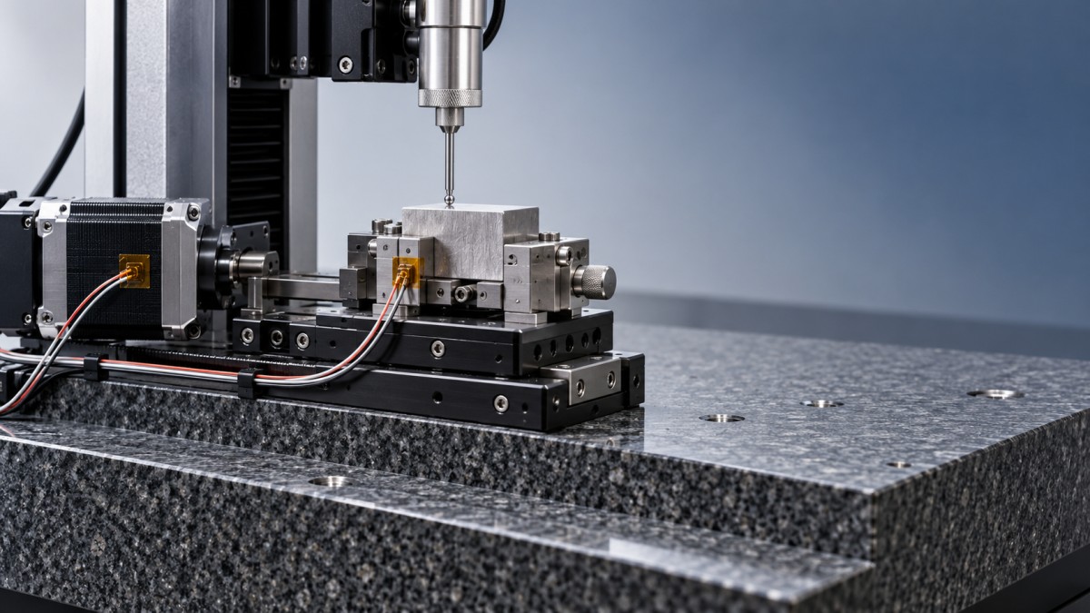
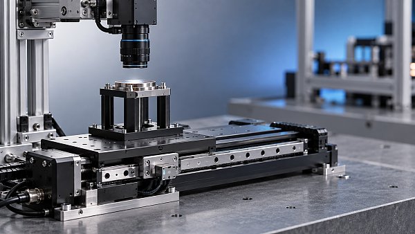
Consider a closed-loop positioning stage carrying a sample beneath a stationary objective. Its encoder measures carriage position relative to a scale. It does not necessarily measure expansion of the objective support, distortion of the sample holder, or motion between the encoder reference and the process point. Holding the encoder reading constant may therefore leave the relevant working distance unstable.
The useful case study identifies the complete measurement loop: sensor, reference structure, moving assembly, fixture, workpiece, and process interface. Without that map, “position stability” is ambiguous. Stability at the carriage is not automatically stability at the cutting edge, probe tip, or optical focus.
Sensor placement also determines sensitivity to angular motion. If a measurement axis is offset from the functional point, small thermally induced rotations can produce an Abbe error. This is why a convincing thermal assessment includes structural geometry, not just a temperature log.
Small temperature changes matter, but uniform expansion is only the starting point
For a freely expanding, approximately uniform component, the familiar estimate is ΔL = α × L × ΔT. As an illustrative calculation, a 100 mm component with an assumed expansion coefficient of 10 × 10−6/K changes length by 100 nm for a uniform 0.1 K temperature rise. This is a sensitivity calculation, not a measured project result or a universal material property.
Real assemblies are less cooperative. Different materials expand differently; bolted interfaces constrain movement; local heating bends structures rather than simply lengthening them. A low-expansion base does not cancel growth in a mounting bracket, adhesive layer, or sample carrier. Material data also need to match the actual grade and operating temperature.
A room-temperature trace alone cannot resolve these effects. Supply air may remain stable while a motor mount warms locally. A fixture may cool after loading while the machine frame continues warming. Two operating states with the same ambient reading can therefore produce different positioning errors.
For this reason, thermal gradients and time histories usually deserve more attention than a single environmental tolerance. Look for measurements near heat sources, critical interfaces, and the workpiece—not merely on the enclosure wall.
Three operating scenarios expose weak thermal evidence
Cold start followed by normal production
A warm-up plot is useful only if its workload resembles the intended process. Idling a spindle or exercising a stage at low acceleration may not reproduce production heat generation. Piezoelectric drive losses, motor duty cycles, vacuum equipment, and nearby electronics can all change the thermal balance.
Ask when the system first meets its acceptance criterion and whether it stays there. “Ready after warm-up” should mean a defined error threshold over a defined observation interval, not simply completion of a timer. A system requiring lengthy stabilization may still be suitable for continuous operation, but less attractive for frequent short runs.
A stable machine receives a new workpiece
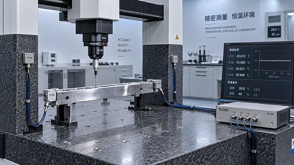
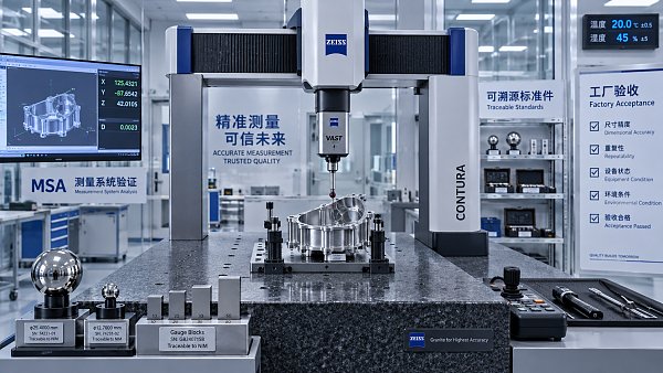
Machine stability does not establish workpiece stability. A component brought from another room can continue changing size after clamping. Handling adds heat, and the fixture changes both heat transfer and mechanical constraint. On a CMM, compensation based on one surface sensor may not represent the temperature throughout a thick or complex part.
Useful evidence records part conditioning, loading sequence, fixture contact, and the delay before measurement. Otherwise, apparent machine drift may actually be workpiece equilibration—or the reverse.
The duty cycle changes after qualification
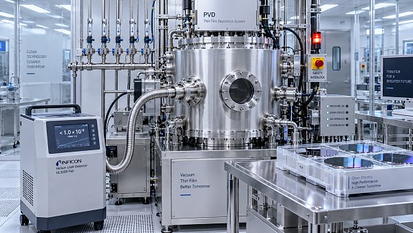
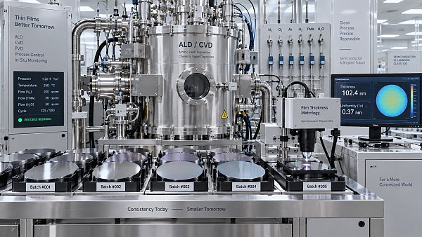
An accuracy-critical stage may behave well during repeated short moves but drift during sustained scanning. A fluid-control assembly may introduce a different disturbance when flow or inlet temperature changes. In thin-film equipment, substrate heating and chamber-related thermal transients can affect alignment independently of stage feedback.
These are evaluation scenarios, not reported customer outcomes. Their purpose is to test whether a case study covers the actual operating envelope. A result obtained under one motion profile should not be extended to another without supporting evidence.
Compensation needs evidence outside its calibration conditions
Thermal management normally combines heat reduction, structural design, environmental control, and compensation. None is automatically the best choice. Moving electronics away from the metrology structure may reduce local heating but complicate cabling. Active cooling can remove heat while introducing vibration, flow fluctuations, or new gradients. Low-expansion materials can reduce sensitivity without addressing interface motion.
Software compensation is valuable when temperature measurements reliably predict the relevant displacement. The difficult part is proving that relationship beyond the dataset used to build it. A model fitted to one warm-up run may struggle after a shutdown, a different payload, or a reversed thermal transient.
Look for independent validation runs and both uncompensated and compensated results. Residual error should be reported over time and across relevant positions, not only as one averaged improvement. An average can conceal a short excursion that ruins a measurement or processing step.
Temperature-sensor response time matters here. A sensor mounted near a heat source may respond faster than the structure it represents, or much slower than the disturbance affecting the process. Thermal lag can make a simple temperature-to-displacement correction unreliable during transitions even if it works at equilibrium.
Standards help define the test—not guarantee the application
ISO 230-3 addresses determination of thermal effects for machine tools. It provides a relevant framework where that equipment and test scope apply; it is not a blanket qualification for every nanopositioning or metrology platform. CMM performance evidence may instead reference applicable parts of the ISO 10360 series. The exact part, edition, machine configuration, and test conditions need checking.
ISO 1 establishes 20 °C as the standard reference temperature for geometrical and dimensional properties. That reference does not mean every precision process must operate at 20 °C. It means dimensional results need an appropriate relationship to the reference temperature, with material expansion and uncertainty handled where relevant.
A credible report distinguishes compliance with a specified test from fitness for a particular process. A standardized test may not reproduce a heated substrate, an unusual fixture, or long-duration scanning. Supplemental application tests can therefore be necessary without implying that the standard test is inadequate.
The measurement method needs scrutiny too. Laser interferometry can be affected by air refractive-index changes, while its mounting structure can move thermally. Apparent machine drift may include measurement-system drift. Traceable calibration, environmental correction, and an uncertainty budget help determine how much confidence the reported displacement deserves.
What to request before comparing project cases
A concise evidence request often reveals more than another specification sheet. For each candidate system, ask for:
- A defined measurand: displacement at which point, along which axis, relative to which reference.
- A complete test timeline: initial thermal state, warm-up, workload changes, interruptions, and measurement duration.
- Synchronized records: displacement, relevant temperatures, motion commands, and operating events on a common time base.
- Disclosed data processing: filtering, averaging, detrending, zero resets, and excluded intervals.
- A repeatability check: whether the thermal response returns across separate runs, rather than merely looking smooth once.
Zero resets deserve particular attention. Re-zeroing after stabilization may be legitimate for the process, but it removes the startup offset from the displayed result. Likewise, detrending can help diagnose vibration while hiding the slow movement that a thermal-drift assessment is supposed to quantify. Neither practice is inherently wrong; undisclosed use is the problem.
For Global Ultra-Precision Engineering (G-UPE), the practical value of cross-sector benchmarking is connecting these dependencies. Metrology, nano-positioning, fluid control, and thin-film processes may be assessed separately, yet their thermal effects meet at the same functional interface. Comparable evidence requires a shared definition of operating conditions and residual error, not just a common accuracy unit.
Before accepting a thermal-stability claim, request the time-resolved error record under the intended workload, alongside the sensor locations and processing history. If the supplier can explain what moved, why it moved, and what remains after correction, the case is useful. If the evidence stops at resolution and a stable room temperature, the main engineering question is still unanswered.
Recent Articles
 2026.10.21NTT, Furukawa Electric and Partners Launch Photonics Mass-Production R&DExplore NTT and Furukawa Electric's photonics mass-production R&D with partners, targeting scalable chip manufacturing for energy-efficient AI computing and higher-bandwidth data centers.
 2026.10.21What ultra-precision engineering case studies reveal about thermal driftExplore ultra-precision engineering project cases to uncover hidden thermal drift, assess compensation, and learn what evidence to request before choosing a precision system.
 2026.10.20BASF Signs Letter of Intent with Taiwan Ministry to Expand Guanyin Semiconductor MaterialsBASF’s planned Guanyin semiconductor materials expansion targets sub-2nm manufacturing. Explore what its letter of intent with Taiwan’s Ministry of Economic Affairs could mean for chipmakers.
 2026.10.20How to estimate medical technology costs beyond the purchase priceEstimate medical technology cost beyond the purchase price. Uncover hidden expenses, compare lifecycle costs, and use this guide to make smarter procurement decisions.
 2026.10.1960 Minutes: Iran War Drives Global Helium Shortage, Threatening Semiconductor SupplyIran war-linked global helium shortage reportedly threatens semiconductor supply. Explore chipmaking risks and practical steps to verify inventories, shipments and supplier commitments.
 2026.10.19How to specify zinc coating weight for prepainted GI steel coilsSpecify zinc coating weight for prepainted gi steel coils with confidence. Learn how to define Z275, compare standards, and verify compliance to avoid costly purchasing mistakes.
 2026.10.18How linear motor stage settling time affects inspection throughputOptimize your linear motor stage for inspection systems: learn how settling time, vibration, and exposure timing affect throughput—and boost inspection output without sacrificing accuracy.
 2026.10.17Choosing a microfluidic probe manufacturer for stable flow confinementChoose a micro fluidic probe manufacturer with proven flow confinement. Compare geometry, flow control, validation, and repeatability to find the right fit for your application.
 2026.10.16What does measurement accuracy specified as % of full scale mean?Understand measurement specification accuracy as % of full scale. Learn to calculate error, compare sensor ranges, and choose the right instrument with confidence.
 2026.10.15How temperature affects high-accuracy dimensional analysis systemsDiscover how temperature affects high accuracy dimensional analysis systems, and learn practical ways to control thermal drift, improve compensation, and verify measurement accuracy.
 2026.10.14How air pressure affects precision pneumatic actuator repeatabilityPrecision Pneumatic actuator repeatability depends on more than supply pressure. Discover how pressure, friction, and flow affect positioning—and how to improve consistency in your application.
 2026.10.13How to choose a packaging manufacturer for small production runsChoose a packaging manufacturer for small production runs with confidence. Discover how to compare costs, verify samples, and secure quality packaging without excess inventory.
 2026.10.12SEMI-Compliant Silane Gas: Which Specifications and Test Records Should You Check?SEMI compliant silane gas: Discover the standards, impurity limits, test records, and cylinder traceability checks that support confident purchasing and safer release decisions.
 2026.10.12Ultra-Pure Silane Gas Price: Comparing Quotes Beyond Cost per CylinderCompare ultra-pure silane gas price beyond cylinder costs. Learn how purity, usable quantity, freight, and return terms shape true value—and make a smarter purchasing decision.
 2026.10.12Moisture-Controlled Silane Gas: Tracing Water Contamination in Delivery LinesKeep moisture controlled silane gas reliable. Learn how to validate readings, trace water contamination in delivery lines, and verify recovery with safety-focused diagnostic insights.
 2026.10.12What Does 99.99999% Silane Gas Mean? Understanding 7N Purity and Detection LimitsEvaluate 99.99999 silane gas with confidence. Discover what 7N purity means, how detection limits affect results, and which supplier data to check before qualification.
 2026.10.12Ultra-Pure Silane Gas for Thin Films: Matching Gas Grade to Film RequirementsChoose ultra-pure silane gas for thin films with confidence. Learn to match impurity limits, supplier evidence, and delivery conditions to film requirements while avoiding unnecessary costs.
 2026.10.12Ultra-Pure Silane Gas for PECVD: Linking Impurities to Film DefectsQualify ultra-pure silane gas for PECVD with confidence. Learn how impurities affect film defects and use gas analysis, delivery checks, and film testing to set reliable acceptance limits.
 2026.10.12Qualifying an Ultra-Pure Silane Gas Manufacturer: Batch Consistency and TraceabilityQualify an ultra-pure silane gas manufacturer with confidence. Learn how to verify batch consistency, analytical results, and cylinder traceability to reduce sourcing risks.
 2026.10.12Choosing an Ultra-Pure Silane Gas Supplier: Lead Times, Delivery, and Backup SupplyChoose an ultra-pure silane gas supplier with reliable lead times, compliant delivery, and qualified backup supply. Learn what to verify to protect production and reduce supply risks.
 2026.10.12Ultra-Pure Chemicals in Latin America: What Shapes Regional Supply and Demand?Ultra-pure chemicals Latin America: explore demand drivers, qualified supply, and purity risks to uncover smarter sourcing and investment opportunities.
 2026.10.12Are Electronic Gas Certificates of Analysis Enough to Qualify Suppliers?Are electronic gas certificates of analysis enough for supplier qualification? No. Discover the sampling, testing, packaging and traceability controls needed to qualify suppliers with confidence.
 2026.10.12Which ALD Precursor Specifications Matter for Supplier Qualification?Which ALD precursor specifications matter most for supplier qualification? Explore purity, impurities, delivery, stability, and lot consistency to qualify suppliers with confidence.
 2026.10.12How Should You Validate a Measurement System Before Factory Acceptance?How should I validate a measurement system before factory acceptance? Discover essential FAT checks, traceability, uncertainty, and decision rules to approve equipment with confidence.
 2026.10.12What Risks Should You Check Before Buying Cleanroom Micro-Robots?What risks should I check before buying micro-robots for cleanroom use? Explore contamination, precision, cleaning, and supplier risks to protect yield and buy with confidence.
 2026.10.12How Can You Verify a Thin-Film Deposition Supplier Meets SEMI Standards?How can I verify whether a thin-film deposition supplier meets SEMI requirements? Discover key standards, evidence checks, and acceptance tests to qualify suppliers with confidence.
 2026.10.12How Do You Compare ALD/CVD Suppliers for Process Consistency?How do I compare semiconductor manufacturing suppliers for process consistency? Discover how to assess ALD/CVD film quality, run-to-run stability, and drift controls to select with confidence.
 2026.10.12What Materials Data Is Needed to Qualify a New PVD Target Supplier?Which material science data is essential before qualifying a new supplier? Discover PVD target checks for purity, microstructure, density and bond integrity to qualify suppliers with confidence.
 2026.10.12What Should a Private-Label Photoresist Quality Agreement Include?Build a stronger private label manufacturing quality agreement for photoresist. Discover essential clauses for specifications, batch release, change control, and traceability.
 2026.10.12How Much Does an Optical Tweezers System Cost?Explore optical tweezers system price ranges, key cost drivers, and ownership expenses. Compare configurations and learn how to choose the right setup for your research budget.
 2026.10.12How to size commercial refrigerators for a restaurant kitchenDiscover how commercialrefrigerators should be sized for peak demand, smarter workflow, food safety, and reliable restaurant kitchen performance.
 2026.10.11How procurement planning reduces supply risk in Latin AmericaProcurement planning Latin America helps reduce supply risk with supplier qualification, import readiness, inventory controls, and contingency sourcing.
 2026.10.10How to build a supplier capability evaluation scorecard for critical partsSupplier capability evaluation scorecard: build a risk-based framework with gates, evidence, and weighted criteria to qualify critical-part suppliers with confidence.
 2026.10.09When do sub micron pneumatic actuators improve metrology repeatability?Sub micron pneumatic actuators for metrology improve repeatability by reducing friction, controlling contact force, and accelerating settling time. Discover when they deliver measurable inspection gains.




FILTER_CORE
REF_NO: 0042
Editors' Picks
- 00
0000-00
NTT, Furukawa Electric and Partners Launch Photonics Mass-Production R&D - 00
0000-00
What ultra-precision engineering case studies reveal about thermal drift - 00
0000-00
BASF Signs Letter of Intent with Taiwan Ministry to Expand Guanyin Semiconductor Materials - 00
0000-00
How to estimate medical technology costs beyond the purchase price