
Microassembly of Optical Components: Aligning Parts Without Damage
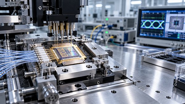
Aligning a miniature lens, fiber, or photonic chip without damage requires control over the entire assembly sequence: pickup, approach, optical optimization, fixation, and release. A positioning stage may reach the required coordinates while a gripper chips an edge, a particle scratches a coating, or curing adhesive pulls the component away from its optical optimum. Successful microassembly must preserve both the component and the alignment after all temporary tooling has been removed.
For engineering project leaders, the most useful starting point is a process window that connects optical performance to allowable motion, contact force, and bonding conditions. Passive alignment can work when component geometry and mechanical datums reliably establish the optical relationship. Active alignment becomes valuable when manufacturing variation or optical sensitivity makes those references insufficient. Either approach needs a handling and fixation strategy matched to the actual component.
Define acceptable alignment through optical performance.
A drawing tolerance alone does not establish whether an optical assembly will function. Lateral displacement, axial spacing, angular error, and rotation affect different optical interfaces differently. A fiber coupling operation may be especially sensitive to transverse position and angle; a lens assembly may also depend strongly on working distance and focus. The team needs to identify which degrees of freedom materially affect the intended optical result before specifying motion hardware.
Where possible, map the acceptable operating region by measuring optical response as position and angle change. The metric might be coupled power, insertion loss, beam position, wavefront quality, or image quality. Use a metric that represents the product’s function. Maximizing total detected power, for example, may provide an incomplete acceptance criterion when polarization, channel balance, or beam shape also matters.
This response map helps allocate tolerances among components, fixtures, positioning, measurement, and bonding. It also reveals whether a search routine has a broad capture region or a narrow peak that requires a carefully established starting position. A project that skips this step risks buying motion resolution that contributes little to yield while overlooking fixture drift or adhesive movement.
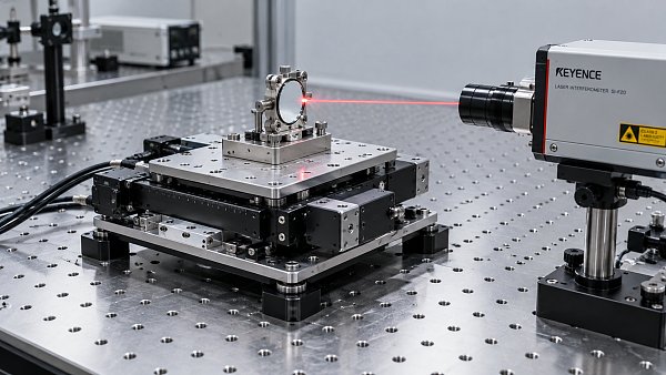
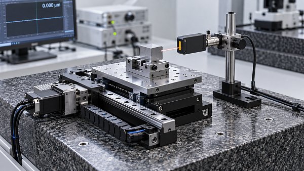
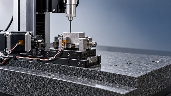
Stage resolution should therefore be assessed alongside repeatability, accuracy, angular errors, settling behavior, and stability under the actual payload. Small commanded increments do not establish equivalent positioning performance at the optical interface. Motion between the stage feedback reference and the component can remain invisible to the position controller. The distance between that reference and the optical interface also matters because angular motion can produce displacement at the component.
Protect the component through a deliberate contact strategy.
Damage prevention begins by identifying where contact is permissible. A mechanical drawing should distinguish functional optical surfaces, coated regions, fragile edges, bonding areas, and approved handling locations. These restrictions need to survive the transition from design to tooling: a gripper that appears suitable in a nominal CAD model may touch an optical surface when part dimensions vary or the component enters at an angle.
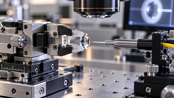
Vacuum pickup, mechanical gripping, and compliant tools each introduce different constraints. Vacuum handling requires a suitable pickup surface and a controlled release; unsuitable contact geometry can concentrate load or leave marks. Mechanical jaws provide positive restraint but can create excessive local stress. Compliant tips can distribute contact pressure, although their deformation may complicate position control or introduce movement during release. Tool materials also need assessment for particle generation, residue, and compatibility with the assembly’s cleanliness requirements.
Force-controlled handling can reduce damage risk when contact is expected, but its effectiveness depends on the complete sensing and motion system. Sensor location, measurement noise, response time, fixture stiffness, and approach speed determine whether the system detects a harmful event early enough. A force reading at the tool mount may not directly reveal the pressure at a small jaw contact or fragile edge.
Establish handling limits through representative component trials and engineering analysis. The operating window must provide enough holding force to resist motion and process loads while remaining below damaging conditions. Include dimensional variation, surface condition, and tool wear in those trials. A setting that works on one nominal sample provides little evidence about performance across the intended production range.
During approach, use a trajectory that keeps the component clear of surrounding structures until it reaches the controlled engagement region. Reduce speed where collision or contact becomes possible, and define a response to unexpected force or missing feedback. Compliance can help absorb contact, but excessive compliance may reduce positioning stability. Its direction and stiffness should suit the task, especially where contact is acceptable along one axis and harmful along another.
Cleanliness belongs within this handling strategy. A trapped particle can change the contact geometry, damage a coating, or prevent a component from seating consistently. Cleaning methods must be compatible with the substrate, coating, adhesive, and package. Inspection before pickup and before final fixation can prevent a contaminated part from becoming an expensive completed assembly.
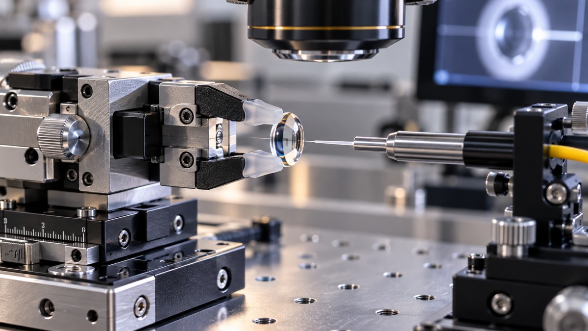
Use optical feedback where mechanical references leave uncertainty.
Passive alignment uses features such as fiducials, grooves, stops, or precision seats to establish component position. It can reduce adjustment time when the relationship between those features and the optical axes is sufficiently controlled. Its feasibility depends on the accumulated variation across the entire interface, including component manufacture, fixture location, seating behavior, and bonding.
Active alignment measures optical performance while moving one or more components. It is useful when the best optical position varies between parts or cannot be inferred adequately from visible geometry. However, it adds requirements for optical access, source stability, detector behavior, control software, and search time. It also requires a safe starting position: an optical optimization routine should not be responsible for discovering physical obstacles.
A practical sequence can combine the two methods. Vision or mechanical references bring the part into a known capture region, followed by optical feedback for final adjustment. This reduces the volume that the optical search must explore. Before approving the sequence, verify that expected part variation still places the interface within that capture region without forcing contact or moving beyond safe travel limits.
The optical measurement itself needs scrutiny. Source fluctuation, detector saturation, stray light, polarization changes, and thermal drift can distort the apparent optimum. If the signal changes independently of motion, the controller may chase measurement variation. Monitor relevant conditions, choose suitable measurement timing, and check that repeated searches return a consistent operating region. Where the response contains multiple peaks, the search strategy must distinguish the intended operating condition from an acceptable-looking local maximum.
Motion coordination also affects safety and efficiency. Sequential axis adjustments can work when interactions are weak; strongly coupled position and angle changes may require a coordinated search. Define travel boundaries and collision constraints before optimization starts. Software limits should reflect the installed tooling and component geometry, including tolerances and approach orientation, rather than only the stage’s available travel.
Carry the alignment through bonding and release.
The highest optical signal reached during adjustment is an intermediate result. The assembly must retain acceptable performance through adhesive application, curing, tool withdrawal, and the operating conditions relevant to the product. These steps deserve explicit development time because they can change both component position and mechanical stress after alignment appears complete.
Adhesive selection involves more than nominal shrinkage. Viscosity, wetting, cure mechanism, bond thickness, stiffness, thermal expansion, and compatibility with optical surfaces all influence the outcome. Adhesive flow can disturb a lightly restrained component or reach a functional surface through capillary action. Dispense volume, location, and timing should therefore be developed together with the holding fixture and alignment sequence.
Bond geometry can influence how curing movement translates into optical displacement. Unequal adhesive distribution or uneven cure exposure can create asymmetric forces. A staged cure may help retain position in some assemblies, but it must provide adequate fixation before the tool releases the part and allow the remaining material to cure as intended. Shadowed regions and limited curing access need consideration during package design.
Monitor optical performance during fixation when access permits. Comparing the aligned, initially fixed, fully cured, and released states helps identify where loss occurs. Movement during cure points toward different causes than movement during tool withdrawal. Release-related changes may involve elastic preload, gripper adhesion, vacuum release behavior, cable forces, or contact between the tool and surrounding material.
Temperature should also be controlled or recorded where it can affect the result. Illumination, curing equipment, actuators, and the device itself can introduce heat. An assembly aligned while temporarily warm may move as it returns to its reference condition. Define when final acceptance occurs and which thermal state it represents. Products exposed to changing temperatures may require additional qualification to establish whether the retained alignment remains adequate.
Evaluate the complete process before committing to production equipment.
An equipment demonstration is most informative when it uses representative components, fixtures, optical feedback, and bonding steps. Ask for evidence of retained performance after release, together with the conditions under which that performance was obtained. A successful alignment on a rigid reference artifact demonstrates only part of the capability needed for a delicate optical assembly.
A focused evaluation should answer four practical questions:
- Can the system acquire parts across the expected dimensional and presentation variation without damaging functional surfaces?
- Can it reach an acceptable optical operating region consistently, within the required cycle time and permitted contact conditions?
- Does the assembly retain that performance through fixation, release, and the specified stabilization period?
- Can recorded process data distinguish handling faults, alignment failures, and bonding-related movement?
Cycle time should include loading, inspection, settling, searching, dispensing, curing, release, and final measurement. Quoting only the optical search time can conceal the operations that determine actual throughput. Similarly, yield should be based on completed assemblies meeting acceptance criteria. Frequent rework or a large loss between alignment and release can undermine an apparently fast process.
For project planning, assign ownership of the interfaces between optics, mechanics, automation, and adhesive processing. Specify who defines the allowable handling locations, validates the optical metric, establishes the bonding window, and approves final acceptance. Record component identity, relevant force events, alignment results, and post-fixation performance at a level that supports fault investigation without overwhelming routine production.
The most useful development milestone is a repeatable sequence that produces an acceptable released assembly across representative variation. If the optical result deteriorates after cure, work on bonding and restraint. If acquisition fails, improve presentation and capture. If damage appears during handling, revisit contact geometry and force control before increasing positioning sophistication. These distinctions keep investment directed toward the operation that actually limits safe, repeatable assembly.
Taglist:
Recent Articles
 2026.10.31Can a supplier capability evaluation checklist reveal capacity risks?A supplier capability evaluation checklist can uncover hidden capacity risks. Learn how to verify available capacity, identify bottlenecks, and protect delivery schedules.
 2026.10.30US Continues Anti-Dumping and Countervailing Duty Orders on Chinese Disposable CylindersUS anti-dumping and countervailing duty orders on Chinese disposable cylinders remain in place. Explore potential sourcing and compliance implications.
 2026.10.30How semiconductor fab expansion affects electronic gas supplyExplore the impact of semiconductor fab expansion on the supply chain, from electronic gas demand and purity to logistics, qualification and sourcing risks.
 2026.10.29How much does a microsurgical robot cost over its service life?Understand micro surgical robot cost over its service life, from purchase and maintenance to instruments and training. Compare lifetime budgets and per-procedure costs to invest with confidence.
 2026.10.28US Energy Department Lists Helium as Critical Material to Secure Semiconductor SupplyHelium joins the US Energy Department's critical materials list. Explore what this means for semiconductor supply security, procurement planning and potential regulatory changes.
 2026.10.28How to check whether body kits will fit your car before buyingWill body kits fit your car? Learn how to verify model compatibility, mounting points, sensor clearance, and return terms before buying to avoid costly mistakes.
 2026.10.27India Hosts 61st CIML Meeting for First Time, Advances International Metrology AlignmentIndia hosts the 61st CIML meeting, highlighting OIML-CS status and legal metrology reforms. Explore what international alignment could mean for instrument certification and equipment trade.
 2026.10.27When should you call emergency medical services instead of driving?When should you call emergency medical services instead of driving? Learn the critical warning signs, why an ambulance can be safer, and what to do while help arrives.
 2026.10.26Mycronic Wins $12–14 Million Photomask System Order from Asian CustomerMycronic secures a $12–14 million photomask system order from an existing Asian customer. Explore the writing and measurement systems and their planned 2027 deliveries.
 2026.10.26Nanometer Motion: Why Positioning Resolution Is Not the Same as AccuracyNanometer motion demands more than fine resolution. Discover how accuracy, repeatability, and calibration reveal true positioning performance—and choose the right system with confidence.
 2026.10.26Microassembly of Optical Components: Aligning Parts Without DamageDiscover how microassembly protects delicate optical components through precise alignment, controlled handling, and reliable bonding. Learn how to reduce damage and retain optical performance.
 2026.10.26What Is Micro Dynamics? Motion and Vibration in Precision MachinesExplore micro dynamics in precision machines: learn how vibration affects accuracy, measure hidden motion, and discover practical ways to improve settling time and performance.
 2026.10.26Reduce CMM Inspection Time Without Compromising Critical Feature ChecksLearn how to reduce CMM inspection time with smarter probe paths, repeatable setups, and validated sampling—while preserving critical feature checks and reliable results.
 2026.10.26Analytical Fluid Control: Choosing Valves for Low-Volume Sample HandlingOptimize analytical fluid control with valves that protect low-volume samples. Discover how to reduce carryover, preserve analyte recovery, and validate reliable dosing.
 2026.10.26The Future of Precision Fluid Control: Smarter Dosing in Semiconductor FabsExplore the future of precision fluid control in semiconductor fabs. Discover how smarter dosing, closed-loop control, and predictive diagnostics improve repeatability and protect purity.
 2026.10.26Benefits of Precision Fluid Control: When Do Chemical Savings Justify Cost?Explore the benefits of precision fluid control: reduce chemical waste, assess ownership costs, and calculate payback to see when savings justify your investment.
 2026.10.26Developing Precision Fluid Control Systems: From Flow Specs to ValidationExplore the development of precision fluid control systems, from flow specs to validation. Learn how to select components, reduce risk, and verify real-world performance.
 2026.10.26Piezoelectric Actuator Selection: Balancing Stroke, Force, and BandwidthSelect the right piezoelectric actuator by balancing loaded stroke, force, and bandwidth. Explore key design checks to improve precision and avoid costly sizing mistakes.
 2026.10.26Layer Deposition Equipment: ALD vs. CVD for High-Aspect-Ratio FeaturesCompare layer deposition equipment for high-aspect-ratio features. Explore ALD vs. CVD conformality, throughput, and costs to choose the right system with confidence.
 2026.10.26Checking repeatability in bulk orders of encoder-feedback nano stagesCompare encoder feedback nano-positioning stage wholesale offers using repeatability tests, lot acceptance criteria, and traceable reports. Learn how to reduce risk and buy with confidence.
 2026.10.25Sidea Semiconductor Granted Patent for Probe Card Alignment CalibrationSidea Semiconductor's probe card alignment calibration patent aims for precise, low-cost automation without a calibration target. Explore its potential for semiconductor testing.
 2026.10.25How to assess long-term drift in a high-stability laser interferometerAssess long-term drift in a high stability laser interferometer with reliable reference tests, environmental tracking, and clear acceptance limits. Learn how to validate lasting measurement accuracy.
 2026.10.24SIA Submits Comments to EPA on Draft Trans-DCE Risk AssessmentSIA backs EPA’s draft Trans-DCE risk assessment for semiconductor manufacturing. Explore what its comments could mean for continued lawful use, supply stability, and production planning.
 2026.10.24How to size plastic extrusion machines for your target outputSize plasticextrusionmachines for your target output with practical throughput calculations, resin checks, and line-capacity tips. Avoid costly sizing mistakes and choose with confidence.
 2026.10.23Leadmicro Showcases Full ALD, CVD and PVD Lineup at Bay Area Semiconductor ExpoExplore Leadmicro’s ALD, CVD and PVD lineup at the Bay Area Semiconductor Expo, including magnetron sputtering solutions and key checks for smarter equipment procurement.
 2026.10.23How much does closed-loop control add to the price of PZT drivers?Understand PZT drivers price increases for closed-loop control. Compare sensors, electronics, and installation costs to make a smarter purchasing decision.
 2026.10.22Leadmicro Adds PVD Products, Expanding ALD, CVD and PVD CoverageLeadmicro expands ALD, CVD and PVD coverage with new iMagtron PVD products and a ruthenium ALD process. Explore what these advances mean for thin-film deposition and equipment buyers.
 2026.10.22What limits commercial adoption of micro-robotics in Latin America?Micro-robotics Latin America: What limits commercial adoption? Explore costs, integration hurdles, and service gaps—and learn how to reduce investment risks.
 2026.10.21NTT, Furukawa Electric and Partners Launch Photonics Mass-Production R&DExplore NTT and Furukawa Electric's photonics mass-production R&D with partners, targeting scalable chip manufacturing for energy-efficient AI computing and higher-bandwidth data centers.
 2026.10.21What ultra-precision engineering case studies reveal about thermal driftExplore ultra-precision engineering project cases to uncover hidden thermal drift, assess compensation, and learn what evidence to request before choosing a precision system.
 2026.10.20BASF Signs Letter of Intent with Taiwan Ministry to Expand Guanyin Semiconductor MaterialsBASF’s planned Guanyin semiconductor materials expansion targets sub-2nm manufacturing. Explore what its letter of intent with Taiwan’s Ministry of Economic Affairs could mean for chipmakers.
 2026.10.20How to estimate medical technology costs beyond the purchase priceEstimate medical technology cost beyond the purchase price. Uncover hidden expenses, compare lifecycle costs, and use this guide to make smarter procurement decisions.
 2026.10.1960 Minutes: Iran War Drives Global Helium Shortage, Threatening Semiconductor SupplyIran war-linked global helium shortage reportedly threatens semiconductor supply. Explore chipmaking risks and practical steps to verify inventories, shipments and supplier commitments.
 2026.10.19How to specify zinc coating weight for prepainted GI steel coilsSpecify zinc coating weight for prepainted gi steel coils with confidence. Learn how to define Z275, compare standards, and verify compliance to avoid costly purchasing mistakes.










FILTER_CORE
REF_NO: 0042
Editors' Picks
- 00
0000-00
Can a supplier capability evaluation checklist reveal capacity risks? - 00
0000-00
US Continues Anti-Dumping and Countervailing Duty Orders on Chinese Disposable Cylinders - 00
0000-00
How semiconductor fab expansion affects electronic gas supply - 00
0000-00
How much does a microsurgical robot cost over its service life?