
Reduce CMM Inspection Time Without Compromising Critical Feature Checks
A coordinate measuring machine becomes a production bottleneck when finished parts arrive faster than inspection reports can be released. Pressure to clear the queue can lead to shorter scans, fewer probing points, or faster motion—changes that may weaken detection of an out-of-position bore, distorted sealing face, or other safety-critical defect.
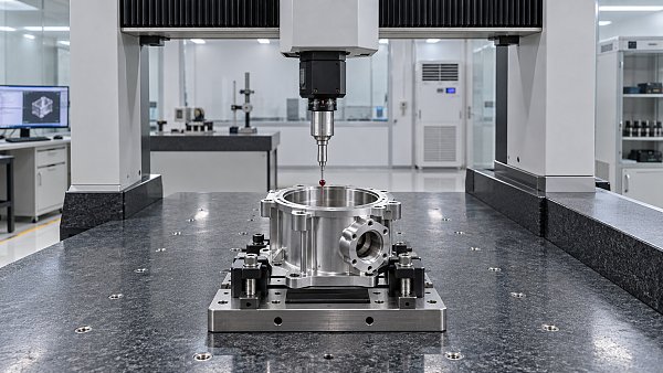
To reduce CMM inspection time without compromising critical feature checks, remove unnecessary travel, repeated setups, and redundant measurement operations first. Then optimize acquisition settings only where validation shows that the revised method preserves required coverage, measurement uncertainty, and acceptance decisions. The objective is a shorter, defensible inspection process—not simply a faster program.
Separate machine cycle time from the inspection queue
Before editing the program, establish where time is actually being lost. A long elapsed inspection time may include waiting for temperature stabilization, locating fixtures, qualifying probes, correcting alignment failures, or manually preparing reports. Shortening the probing routine will not solve a bottleneck dominated by those activities.
Record several representative runs rather than relying on the program’s estimated duration. Include normal loading variation and routine operator intervention. Separate first-piece inspection from repeat production inspection because their verification requirements and setup demands may differ.
Keep two performance measures: machine occupancy per accepted inspection and elapsed time to a released result. A faster routine that produces more reruns may improve neither.
Define what the shorter routine must still prove
Start with the drawing, applicable product requirements, approved inspection plan, and relevant process risk analysis. Identify characteristics whose failure could affect safety, fit, sealing, load transfer, or regulatory conformity. Do not assume that the tightest dimensional tolerance is automatically the most critical characteristic.
For each critical characteristic, document the datum reference frame, evaluation method, measurement region, required coverage, and acceptance rule. Include any customer-mandated method or sampling requirement. A feature control frame may require more than a nominal size result: position, orientation, form, and datum simulation can each affect the conclusion.
- Preserve datum integrity. Reducing datum measurements can change alignment stability and shift every dependent result.
- Distinguish point count from coverage. Closely spaced points in one accessible area cannot establish the condition of an entire functional surface.
- Keep required inspection frequency separate from program optimization. Measuring fewer parts is a control-plan change, not merely a cycle-time improvement.
- Identify shared measurements. One acquisition may support several evaluations, provided its location, density, and measurement method satisfy each requirement.
A bore measured for diameter might also support position evaluation. However, a single circular section may not adequately characterize axis direction, taper, or cylindricity. Reusing data is useful only when the acquisition supports the characteristic being reported.
Remove avoidable motion before reducing measurement coverage
Probe travel between features is often the lowest-risk place to start. Programs developed through successive drawing revisions may repeatedly cross the part, revisit the same region, or change probe orientation more often than necessary. Group compatible measurements by location and stylus orientation while retaining the required alignment sequence.
Review approach distances and retract heights individually. Large clearances may be necessary around clamps, deep pockets, and uncertain loading positions, but excessive clearance on unobstructed surfaces adds travel without adding measurement information. Never apply a global clearance reduction without checking the complete swept volume of the probe assembly.
Offline simulation can reveal inefficient routes and potential collisions, but it depends on accurate models of the part, fixture, probe, and machine environment. Follow simulation with a controlled prove-out using the machine’s approved operating procedures. Shorter routes must remain safe under permitted loading variation, not just at the nominal CAD position.
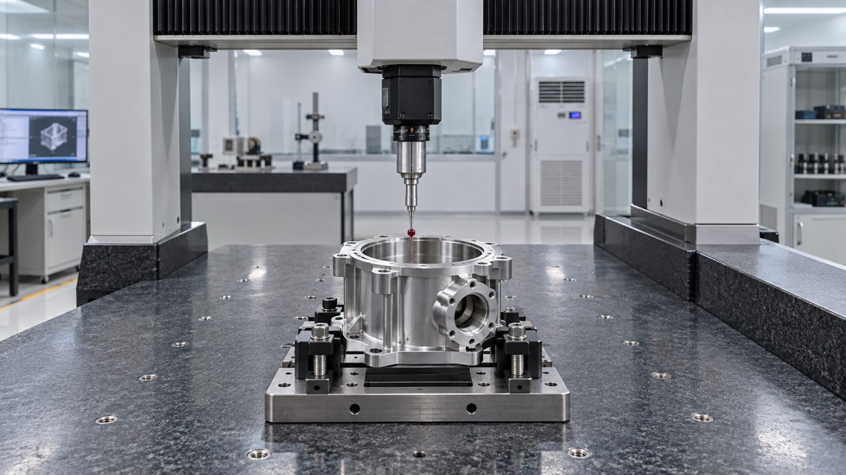
Probe configuration also affects cycle time. A different qualified stylus arrangement may avoid repeated indexing or tool changes, but longer extensions can increase deflection sensitivity and restrict access. Evaluate the complete configuration rather than choosing the arrangement with the fewest changes.
Increase non-measuring travel speed only within machine, controller, probe, and fixture limits. Measuring speed and acceleration require separate scrutiny because they can influence dynamic behavior. A setting suitable for open travel is not automatically suitable for scanning a tight-tolerance feature.
Match point distribution and scanning to the defect you need to detect
The minimum number of points needed to calculate a geometric element is not a defensible inspection strategy by itself. A circle can be mathematically constructed from very few points, yet sparse sampling may miss lobing or local damage. Similarly, limited plane measurements can overlook distortion between sampled locations.
Choose coverage based on plausible manufacturing errors and functional requirements. Bores may need measurements at multiple depths; sealing faces may require coverage across the contact region; long datum surfaces may require sampling that captures twist or bow. Preserve sensitivity to the defect modes that matter.
When fewer points may be justified
Reduced sampling can be considered where process knowledge and comparative measurements demonstrate that the revised distribution still detects relevant variation. Use representative parts spanning expected process conditions, not only a nominal part with smooth surfaces. Suspected tool wear patterns, edge effects, and form deviations should inform the comparison.
A stable process can support a controlled review of the inspection strategy, but capability indices alone do not prove that a sparse measurement method detects all important defects. A process shift or changed tooling may invalidate the assumptions behind the faster routine.
When scanning needs more than a speed adjustment
Continuous scanning can collect substantial surface information efficiently, but more recorded points do not necessarily provide better usable evidence. Scan speed, effective point spacing, filtering, stylus behavior, and surface condition interact. Faster scanning may alter measured form or round transitions that the evaluation needs to retain.
Compare the resulting characteristic values and defect sensitivity, not just the number of points collected. Keep filtering and fitting methods controlled during the comparison; changing acquisition, filtering, and evaluation simultaneously makes disagreement difficult to diagnose.
Make the setup repeatable enough to support the faster path
A shorter program is fragile when the operator must repeatedly reposition the part. Fixtures should constrain the part predictably without distorting it or obstructing critical surfaces. Flexible walls, thin sections, and compliant materials require particular attention to support location and clamping force.
Use repeatable locating features to reduce searching and manual alignment, but do not confuse fixture location with the drawing’s datum system. The program must still establish the required reference frame unless an approved method explicitly provides otherwise.
Part cleanliness and temperature remain measurement controls, not optional preparation steps. Chips beneath a locator can change seating; coolant residue can affect probing; thermal gradients can shift dimensions during the run. Moving preparation outside the CMM cycle can save occupancy, but stabilization criteria must remain appropriate for the material, tolerance, and environment.
Routine probe qualification should follow the approved method and respond to changes such as stylus replacement, suspected contact damage, or configuration changes. Do not extend qualification intervals solely to meet a throughput target. Investigate excessive qualification time through configuration planning and evidence of stability.
Validate the revised routine before using it for release
Run the existing and proposed methods under controlled conditions. The existing routine is a useful comparator, but it is not automatically a reference truth. Where necessary, use a more comprehensive measurement strategy, suitable calibrated artifact, or independent method to investigate differences.
- Define acceptance criteria before testing. Specify acceptable differences, repeatability, coverage, and decision behavior in relation to the tolerance and measurement uncertainty.
- Select challenging parts. Include relevant form variation, different setups, and parts near specification limits where available. Do not intentionally release nonconforming material to create a comparison set.
- Repeat the measurement. Check both repeated cycles and unloading/reloading effects. Include operator variation where manual activities influence results.
- Review characteristic-level results. Look for systematic shifts, increased scatter, missed deviations, and changed pass/fail decisions rather than averaging everything into one agreement figure.
- Assess measurement uncertainty. Reconsider contributions affected by speed, sampling, probe configuration, temperature, and alignment. Good repeatability alone does not establish adequate accuracy.
For results close to a specification limit, apply the agreed conformity decision rule, including any uncertainty treatment or guard band. Do not accept a faster routine simply because both methods report “pass” on parts comfortably inside tolerance.
Machine performance verification provides important evidence about the CMM’s condition, but it does not by itself validate every application-specific program. Difficult geometries, unusual styli, and demanding uncertainty requirements may require a metrology specialist to establish an appropriate task-specific assessment.
Release the improvement with controls that survive the next change
Store the approved program revision together with probe configuration, fixture identification, evaluation settings, validation evidence, and report template. Protect the released routine from uncontrolled editing. Where critical checks are mandatory, make missing or failed acquisition visible and prevent incomplete results from being treated as a successful inspection.
After release, monitor cycle duration alongside rerun frequency, alignment failures, measurement trends, and disagreements with downstream checks. Investigate a sudden reduction in cycle time as well as an increase: skipped features or incorrect program branches can make a routine appear unusually efficient.
Define review triggers such as fixture modification, stylus changes, machine service, software updates affecting evaluation, drawing revisions, and changes to the manufacturing process. Retain a controlled fallback routine for situations where the optimized method cannot establish a valid result. When a critical feature cannot be measured with the required confidence inside the available cycle, the remaining constraint is capacity or method suitability—not permission to omit the check.
Taglist:
Recent Articles
 2026.10.30US Continues Anti-Dumping and Countervailing Duty Orders on Chinese Disposable CylindersUS anti-dumping and countervailing duty orders on Chinese disposable cylinders remain in place. Explore potential sourcing and compliance implications.
 2026.10.30How semiconductor fab expansion affects electronic gas supplyExplore the impact of semiconductor fab expansion on the supply chain, from electronic gas demand and purity to logistics, qualification and sourcing risks.
 2026.10.29How much does a microsurgical robot cost over its service life?Understand micro surgical robot cost over its service life, from purchase and maintenance to instruments and training. Compare lifetime budgets and per-procedure costs to invest with confidence.
 2026.10.28US Energy Department Lists Helium as Critical Material to Secure Semiconductor SupplyHelium joins the US Energy Department's critical materials list. Explore what this means for semiconductor supply security, procurement planning and potential regulatory changes.
 2026.10.28How to check whether body kits will fit your car before buyingWill body kits fit your car? Learn how to verify model compatibility, mounting points, sensor clearance, and return terms before buying to avoid costly mistakes.
 2026.10.27India Hosts 61st CIML Meeting for First Time, Advances International Metrology AlignmentIndia hosts the 61st CIML meeting, highlighting OIML-CS status and legal metrology reforms. Explore what international alignment could mean for instrument certification and equipment trade.
 2026.10.27When should you call emergency medical services instead of driving?When should you call emergency medical services instead of driving? Learn the critical warning signs, why an ambulance can be safer, and what to do while help arrives.
 2026.10.26Mycronic Wins $12–14 Million Photomask System Order from Asian CustomerMycronic secures a $12–14 million photomask system order from an existing Asian customer. Explore the writing and measurement systems and their planned 2027 deliveries.
 2026.10.26What Is Micro Dynamics? Motion and Vibration in Precision MachinesExplore micro dynamics in precision machines: learn how vibration affects accuracy, measure hidden motion, and discover practical ways to improve settling time and performance.
 2026.10.26Reduce CMM Inspection Time Without Compromising Critical Feature ChecksLearn how to reduce CMM inspection time with smarter probe paths, repeatable setups, and validated sampling—while preserving critical feature checks and reliable results.
 2026.10.26Analytical Fluid Control: Choosing Valves for Low-Volume Sample HandlingOptimize analytical fluid control with valves that protect low-volume samples. Discover how to reduce carryover, preserve analyte recovery, and validate reliable dosing.
 2026.10.26The Future of Precision Fluid Control: Smarter Dosing in Semiconductor FabsExplore the future of precision fluid control in semiconductor fabs. Discover how smarter dosing, closed-loop control, and predictive diagnostics improve repeatability and protect purity.
 2026.10.26Benefits of Precision Fluid Control: When Do Chemical Savings Justify Cost?Explore the benefits of precision fluid control: reduce chemical waste, assess ownership costs, and calculate payback to see when savings justify your investment.
 2026.10.26Developing Precision Fluid Control Systems: From Flow Specs to ValidationExplore the development of precision fluid control systems, from flow specs to validation. Learn how to select components, reduce risk, and verify real-world performance.
 2026.10.26Piezoelectric Actuator Selection: Balancing Stroke, Force, and BandwidthSelect the right piezoelectric actuator by balancing loaded stroke, force, and bandwidth. Explore key design checks to improve precision and avoid costly sizing mistakes.
 2026.10.26Layer Deposition Equipment: ALD vs. CVD for High-Aspect-Ratio FeaturesCompare layer deposition equipment for high-aspect-ratio features. Explore ALD vs. CVD conformality, throughput, and costs to choose the right system with confidence.
 2026.10.26Checking repeatability in bulk orders of encoder-feedback nano stagesCompare encoder feedback nano-positioning stage wholesale offers using repeatability tests, lot acceptance criteria, and traceable reports. Learn how to reduce risk and buy with confidence.
 2026.10.25Sidea Semiconductor Granted Patent for Probe Card Alignment CalibrationSidea Semiconductor's probe card alignment calibration patent aims for precise, low-cost automation without a calibration target. Explore its potential for semiconductor testing.
 2026.10.25How to assess long-term drift in a high-stability laser interferometerAssess long-term drift in a high stability laser interferometer with reliable reference tests, environmental tracking, and clear acceptance limits. Learn how to validate lasting measurement accuracy.
 2026.10.24SIA Submits Comments to EPA on Draft Trans-DCE Risk AssessmentSIA backs EPA’s draft Trans-DCE risk assessment for semiconductor manufacturing. Explore what its comments could mean for continued lawful use, supply stability, and production planning.
 2026.10.24How to size plastic extrusion machines for your target outputSize plasticextrusionmachines for your target output with practical throughput calculations, resin checks, and line-capacity tips. Avoid costly sizing mistakes and choose with confidence.
 2026.10.23Leadmicro Showcases Full ALD, CVD and PVD Lineup at Bay Area Semiconductor ExpoExplore Leadmicro’s ALD, CVD and PVD lineup at the Bay Area Semiconductor Expo, including magnetron sputtering solutions and key checks for smarter equipment procurement.
 2026.10.23How much does closed-loop control add to the price of PZT drivers?Understand PZT drivers price increases for closed-loop control. Compare sensors, electronics, and installation costs to make a smarter purchasing decision.
 2026.10.22Leadmicro Adds PVD Products, Expanding ALD, CVD and PVD CoverageLeadmicro expands ALD, CVD and PVD coverage with new iMagtron PVD products and a ruthenium ALD process. Explore what these advances mean for thin-film deposition and equipment buyers.
 2026.10.22What limits commercial adoption of micro-robotics in Latin America?Micro-robotics Latin America: What limits commercial adoption? Explore costs, integration hurdles, and service gaps—and learn how to reduce investment risks.
 2026.10.21NTT, Furukawa Electric and Partners Launch Photonics Mass-Production R&DExplore NTT and Furukawa Electric's photonics mass-production R&D with partners, targeting scalable chip manufacturing for energy-efficient AI computing and higher-bandwidth data centers.
 2026.10.21What ultra-precision engineering case studies reveal about thermal driftExplore ultra-precision engineering project cases to uncover hidden thermal drift, assess compensation, and learn what evidence to request before choosing a precision system.
 2026.10.20BASF Signs Letter of Intent with Taiwan Ministry to Expand Guanyin Semiconductor MaterialsBASF’s planned Guanyin semiconductor materials expansion targets sub-2nm manufacturing. Explore what its letter of intent with Taiwan’s Ministry of Economic Affairs could mean for chipmakers.
 2026.10.20How to estimate medical technology costs beyond the purchase priceEstimate medical technology cost beyond the purchase price. Uncover hidden expenses, compare lifecycle costs, and use this guide to make smarter procurement decisions.
 2026.10.1960 Minutes: Iran War Drives Global Helium Shortage, Threatening Semiconductor SupplyIran war-linked global helium shortage reportedly threatens semiconductor supply. Explore chipmaking risks and practical steps to verify inventories, shipments and supplier commitments.
 2026.10.19How to specify zinc coating weight for prepainted GI steel coilsSpecify zinc coating weight for prepainted gi steel coils with confidence. Learn how to define Z275, compare standards, and verify compliance to avoid costly purchasing mistakes.
 2026.10.18How linear motor stage settling time affects inspection throughputOptimize your linear motor stage for inspection systems: learn how settling time, vibration, and exposure timing affect throughput—and boost inspection output without sacrificing accuracy.
 2026.10.17Choosing a microfluidic probe manufacturer for stable flow confinementChoose a micro fluidic probe manufacturer with proven flow confinement. Compare geometry, flow control, validation, and repeatability to find the right fit for your application.
 2026.10.16What does measurement accuracy specified as % of full scale mean?Understand measurement specification accuracy as % of full scale. Learn to calculate error, compare sensor ranges, and choose the right instrument with confidence.




















FILTER_CORE
REF_NO: 0042
Editors' Picks
- 00
0000-00
US Continues Anti-Dumping and Countervailing Duty Orders on Chinese Disposable Cylinders - 00
0000-00
How semiconductor fab expansion affects electronic gas supply - 00
0000-00
How much does a microsurgical robot cost over its service life? - 00
0000-00
US Energy Department Lists Helium as Critical Material to Secure Semiconductor Supply