
Laser Interferometer Systems Alignment: Common Errors and Fixes
Laser interferometer systems alignment tends to fail in small, ordinary ways before it fails dramatically. A slight beam offset, a warm machine base, or a loose optic mount can turn a stable setup into drifting data.
In precision production and service environments, those errors do more than distort measurement. They interrupt calibration, slow fault isolation, and create doubt about motion accuracy, process capability, and acceptance results.
That matters across sectors tracked by G-UPE, where semiconductor positioning, metrology platforms, aerospace assemblies, and micro-manipulation systems all depend on verified alignment discipline, not just nominal specifications.
Why does laser interferometer systems alignment drift even after a setup looked correct?
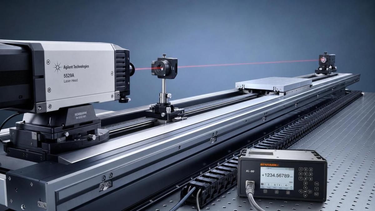
A setup can look visually straight and still be wrong at the measurement level. Laser interferometer systems alignment is sensitive to angular error, cosine error, Abbe offset, vibration, and thermal growth.
The common trap is assuming initial beam capture equals correct alignment. It does not. If the return beam is weak, clipped, or unstable, the system may still produce numbers while accuracy quietly degrades.
In actual field work, drift usually comes from combined causes rather than one obvious fault. A slightly misaligned optic may become critical only after machine temperature rises or a stage accelerates harder.
Another overlooked factor is installation context. Laser interferometer systems alignment on a lab bench is easier than alignment on production equipment surrounded by pneumatic lines, cable drag, coolant haze, and intermittent floor vibration.
A useful working rule is simple: if signal quality changes during travel, dwell, or restart, treat alignment as dynamic, not static. The optical path must stay valid through the full machine motion envelope.
What mistakes cause the biggest alignment errors during service work?
Some errors are far more common than others. They usually appear during rushed recovery work, component replacement, or machine relocation.
- Mounting the laser head on a surface that moves or twists during axis travel.
- Aligning to the reflector at one position only, not across the full stroke.
- Ignoring beam height relative to the machine’s actual line of motion.
- Leaving contamination on optics, especially after transport or maintenance.
- Tightening brackets after alignment without checking beam shift again.
- Using nearby heat sources, fans, or open enclosures during final verification.
Beam height matters because misalignment is not only sideways. If the beam is displaced from the axis centerline, Abbe error can amplify a small angular deviation into a meaningful position error.
Contamination is also underestimated. A thin film on optics may not block the beam, but it can reduce return intensity and create intermittent counting issues, especially on long paths or high-speed moves.
Where laser-interferometer-controlled stages are involved, even cable tension can matter. If a cable bundle nudges a bracket during motion, alignment may appear stable at rest and fail only under acceleration.
A quick fault pattern table helps narrow the cause
When symptoms repeat, matching them to likely causes speeds recovery. The table below is more useful than checking parts at random.
How can you tell whether the problem is alignment, environment, or the machine itself?
This is where many service visits lose time. The reading looks bad, but the bad reading does not always mean poor laser interferometer systems alignment.
A better approach is to separate the system into three layers: optical path, local environment, and machine motion behavior. Each layer leaves different clues.
If the return signal fluctuates while the machine is stationary, start with optics and air path. Look for contamination, beam clipping, loose mounts, or air disturbance from fans and doors.
If the signal is clean at rest but unstable during travel, attention shifts toward stage straightness, bracket rigidity, cable influence, or reflector orientation through motion.
If the signal is stable but positional error remains systematic, the issue may be machine geometry, compensation values, encoder interaction, or a reference mismatch rather than alignment alone.
In high-accuracy environments, G-UPE-style benchmarking logic is helpful here. Verify against recognized standards, controlled conditions, and repeatable checkpoints instead of relying on one pass result.
A practical decision sequence
- Check optical cleanliness and mount tightness before touching compensation.
- Observe signal quality at start, middle, and end of axis travel.
- Repeat the same test after thermal stabilization.
- Compare static and dynamic behavior at identical positions.
- Only after that, judge whether the machine geometry is the primary fault.
What does a reliable fix look like, not just a temporary recovery?
A quick recovery restores a signal. A reliable fix restores confidence. The difference is whether the alignment holds through operating conditions, not just during the adjustment moment.
Start by resetting the mechanical reference points. If the laser head, interferometer optics, reflector, or axis fixture moved during service, do not fine-tune around a shifted baseline.
Then align in stages. First obtain an unobstructed return beam. Next optimize beam centering across the entire stroke. After that, tighten hardware progressively and recheck after every mechanical change.
Many alignment losses happen after the last wrench turn. Brackets can twist slightly during final torque, especially on uneven mounting surfaces or improvised adapters.
Thermal condition should also be part of the fix. If the machine normally runs warm, laser interferometer systems alignment must be verified warm. Cold alignment on a hot process tool often wastes time.
The same applies to surrounding systems. Pneumatic pulses, gas flow changes, enclosure movement, and nearby process equipment can all disturb precision measurement, especially in mixed manufacturing cells.
A durable repair usually includes documentation. Record signal level, travel positions, temperature condition, fixture points, and any changes to optics or mounts. That record makes the next intervention faster and more defensible.
When should you stop adjusting and look for a deeper system issue?
Repeated adjustment without stable improvement is a warning sign. If laser interferometer systems alignment drifts back after every restart, the root cause is often outside the optical settings.
One common example is mechanical instability. A base plate may flex, an axis bearing may wear unevenly, or a reflector mount may resonate only at certain speeds. No amount of careful beam steering fixes that.
Another case is environmental mismatch. A metrology-grade alignment method may be forced into a production area with poor temperature control, air turbulence, and inconsistent isolation. The setup is correct, but the context is wrong.
There are also compliance reasons to pause. In sectors governed by ISO, SEMI, or aerospace documentation discipline, undocumented repeated adjustments can weaken traceability and acceptance confidence.
A deeper review is justified when the same symptom appears after optics replacement, machine transport, software update, or control tuning change. At that point, alignment is part of the story, not the whole story.
Signs that escalation is the smarter move
- Signal quality is good, but measured error remains inconsistent.
- Alignment holds only at one speed or one travel segment.
- The setup changes after enclosure closure or process startup.
- The same fix works briefly, then degrades within hours or days.
- Mechanical or environmental records do not match prior validated conditions.
How do you keep laser interferometer systems alignment stable after the repair?
Long-term stability usually comes from routine controls, not heroic troubleshooting. Once the system is restored, protect the conditions that made the alignment valid.
The most effective practice is to standardize a short verification routine. Check beam condition, return signal trend, mount status, and travel-end behavior before full recalibration is needed.
It also helps to define recheck triggers. Transport, collision events, optic cleaning, bracket replacement, coolant leaks, and nearby equipment relocation should all trigger a fresh alignment review.
In broader ultra-precision operations, this is where institutional knowledge matters. G-UPE’s benchmarking mindset is useful because it treats maintenance data, environmental control, and standards alignment as one system.
The practical takeaway is straightforward. Do not treat laser interferometer systems alignment as a one-time optical task. Treat it as a controlled process tied to mechanics, temperature, documentation, and machine behavior.
If recurring drift continues, the next step is to map the fault by condition: cold versus warm, static versus dynamic, center versus end travel, open versus enclosed. That comparison usually reveals where corrective work should focus.
Recent Articles
 2026.07.15CBP Sets New HTS Code for Piezo ValvesCBP Sets New HTS Code for Piezo Valves: learn how the August 1 reclassification to HTS 8481.80.50 impacts imports, duty treatment, GSP eligibility, and compliance steps before July 31.
 2026.07.15Laser Interferometer Systems Alignment: Common Errors and FixesLaser interferometer systems alignment often fails due to beam offset, thermal drift, and weak mounts. Discover common errors, practical fixes, and proven steps to restore stable, accurate measurement.
 2026.07.15Ultra-Precision Manufacturing: Key Cost Drivers and Quality TradeoffsUltra-precision manufacturing cost drivers go far beyond unit price. Learn how materials, metrology, and supplier capability affect quality, risk, and total cost.
 2026.07.15When a Rapid Prototyping Company Speeds Up Product ValidationA rapid prototyping company speeds product validation by turning design concepts into testable parts fast, helping teams cut risk, avoid rework, and make smarter launch decisions.
 2026.07.15Piezo Quantum Stage Accuracy: What Really Limits Motion Performance?Piezo quantum stage accuracy depends on more than resolution. Learn how drift, feedback, control, and integration shape real motion performance before you buy.
 2026.07.15How to Choose a Hydraulic Press for Sheet Metal Without OverpayingHydraulic press for sheet metal buying guide: compare tonnage, repeatability, tooling fit, and lifecycle cost to avoid overpaying and choose a press that truly fits production.
 2026.07.14ArF Photoresist Chem Prices Jump 12% After Korean FireArF Photoresist Chem prices jump 12% after a Korean fire, with lead times stretching to 14–18 weeks. Learn what this means for semiconductor buyers, wafer fabs, and supply planning.
 2026.07.14Singapore Extends Traceability Rule to X-ray MetrologySingapore extends traceability rules to X-ray metrology from Sept 2026. Learn how IMDA import licensing, NIST/A*STAR calibration certificates, and compliance changes impact suppliers and buyers.
 2026.07.14CBP Sets New HTS Code for Nano-Positioning StagesCBP sets new HTS code 9031.90.85 for nano-positioning stages, cutting MFN duty from 4.2% to 0% while adding ISO 14224 clearance rules. See who is affected and what to do before August 1.
 2026.07.14SEMI F47-2026 Tightens ALD/CVD Skid ComplianceSEMI F47-2026 tightens ALD/CVD skid compliance with real-time MFC audit logging and remote calibration traceability. Learn what changes before Oct 1, 2026 for CE, UL, and KC readiness.
 2026.07.14Japan Tightens Etching Precursor Export ReviewsJapan Tightens Etching Precursor Export Reviews: learn how METI’s new controls on HF, ClF₃, and NF₃–N₂O may disrupt semiconductor supply chains, advanced foundries, and delivery planning.
 2026.07.14Glamping Units: Common Specification Mistakes That Raise Operating CostsGlamping units can look cost-effective upfront but drive higher long-term expenses. Discover the key specification mistakes that increase energy, maintenance, and downtime costs.
 2026.07.14PV Modules in 2026: Efficiency, Degradation, and ROI Benchmarks to WatchPV modules in 2026: compare efficiency, degradation, and ROI benchmarks to identify bankable solar assets, reduce long-term risk, and make smarter procurement decisions.
 2026.07.14Pesticides Selection Guide: Comparing Residual Effect, Crop Safety, and CompliancePesticides selection guide comparing residual effect, crop safety, and compliance. Learn how to reduce residue risk, protect crop quality, and support market access with smarter decisions.
 2026.07.14Accessory Design Basics: Key Factors That Affect Fit, Cost, and ManufacturabilityAccessory design shapes fit, cost, and manufacturability from the start. Learn the key factors that reduce risk, improve precision, and support smarter sourcing decisions.
 2026.07.14Patent Landscape Analysis in Bioprocessing: How to Spot White Space and Filing RiskPatent landscape analysis bioprocessing reveals where white space still exists, how filing risk is shifting, and what smarter IP moves can protect growth and speed scale-up.
 2026.07.13SEMI Starts Nano-Positioning Export PilotSEMI Starts Nano-Positioning Export Pilot: learn how ISO 14067 carbon reporting and third-party performance verification could reshape supplier qualification and procurement access.
 2026.07.13Singapore Tightens CMM Import Traceability RulesSingapore Tightens CMM Import Traceability Rules: learn how IMDA’s new CMM documentation, calibration, and licensing requirements could disrupt shipments and what importers must do now.
 2026.07.13Ultra-High-Purity SiH4 Prices Rise 18% as Shortage DeepensUltra-High-Purity SiH4 prices surge 18% as shortages deepen, lead times hit 14–22 weeks, and stricter purity compliance reshapes semiconductor sourcing worldwide.
 2026.07.13FDA Tightens Piezo Valve Rules for Class II DevicesFDA tightens piezo valve rules for Class II devices: learn how ISO 13485:2023 and batch traceability requirements may affect imports, suppliers, and compliance timelines before Oct 1, 2026.
 2026.07.13EU Tightens SEMI F47-2026 Rules for ALD/CVD ExportsEU Tightens SEMI F47-2026 Rules for ALD/CVD Exports: learn how the new EU compliance mandate affects certification, customs clearance, delivery timelines, and supplier access.
 2026.07.13Wholesale Nano-Positioning Stage for Semiconductor Metrology: Cost vs AccuracyWholesale nano-positioning stage for semiconductor metrology: compare cost, accuracy, drift, and lifecycle risk to choose reliable performance and smarter supplier value.
 2026.07.13What to Check Before Selecting a CNC Machining SupplierCNC machining supplier selection starts with more than price. Learn how to verify quality, traceability, capacity, and total cost before placing your first order.
 2026.07.13Nano Fabrication Tools: Choosing the Right Setup for Process StabilityNano fabrication tools selection starts with process stability. Learn how to compare precision, contamination control, metrology, and lifecycle risk for reliable yield.
 2026.07.13ISO Standards for Precision Engineering Audit: Key Checks and Common GapsISO standards for precision engineering audit: discover the key checks, common gaps, and practical fixes that help manufacturers strengthen compliance, reduce risk, and pass audits with confidence.
 2026.07.13How to Evaluate a CMM Metrology Machine for Tight-Tolerance InspectionCMM Metrology machine evaluation starts with real tolerance demands. Learn how to compare accuracy, repeatability, sensors, software, and stability for confident inspection decisions.
 2026.07.12Singapore Tightens Piezo Valve Import Rules for Medical DevicesSingapore tightens piezo valve import rules for medical devices: learn how HSA PMA, ISO 13485, and life test requirements now affect ventilator and IVD supply chains.
 2026.07.12Etching Precursor Shortage Pushes Q3 Spot Prices Up 12%Etching precursor shortage pushes Q3 spot prices up 12%, tightening semiconductor sourcing and delivery plans. See key risks, contract moves, and substitution options now.
 2026.07.12Japan Tightens Pre-Shipment CMM Calibration RuleJapan Tightens Pre-Shipment CMM Calibration Rule: learn how Japan’s new CMM calibration and JCSS report requirement may affect exports, delivery timelines, and compliance planning before September 2026.
 2026.07.12SEMI Revises ALD/CVD Skid Export Rules for EUSEMI revises ALD/CVD skid export rules for the EU with immediate carbon-footprint and digital passport requirements. See who is affected, what changes now, and how to stay shipment-ready.
 2026.07.12EPA Sets New Purity Traceability Rule for Electronic GasesEPA Sets New Purity Traceability Rule for Electronic Gases: learn how the new EPA rule impacts SiH4, NF3, and WF6 imports, compliance, certification, and supply chain planning before October 2026.
 2026.07.12Tractors Price Guide: New vs Used Cost FactorsTractors price guide comparing new vs used cost factors, from purchase price and maintenance risk to uptime, compliance, and resale value—find the best fit before you buy.
 2026.07.12Measurement Systems Price: What Drives Total Cost?Measurement systems price is shaped by accuracy, sensors, software, compliance, and service. Learn what drives total cost and how to compare quotes for stronger ROI.
 2026.07.12Luxury Apparel Demand Trends to Watch in 2026Luxury apparel demand in 2026 is shifting toward value, traceability, and proven quality. Explore the trends shaping premium growth, pricing power, and smarter brand strategy.






















FILTER_CORE
REF_NO: 0042